Stepper motor config - 17HE19-2004S

Hey Guys, can anyone help me with the config for the stepper motors? All I get is them buzzing.

The board is a Jackpot v1.2 with TMC2209 and 17HE19-2004S steppers

datasheet: https://www.omc-stepperonline.com/index.php?route=product/product/get_file&file=2731/17HE19-2004S(1).pdf

I’ve played around with the micro steps but that makes it either make less or more noise…

I’ve tested with 2 other types, 42HS34(L)-0954JA05-D21 and 42HS48-1204JA05-D21, from an old 3D printer, these work just fine…

Something is wrong with the wiring to your stepper, not the Jackpot config.

From the stepper online site:

Please note that the wiring sequence of 17HE19-2004S and 17HS19-2004S1 is different and they cannot be directly substituted for each other.

Do you have the correct motor cable for your version of the stepper (Not the S1)?

I used the included wires, I even tired the wires of the old/spare/laying around steppers. I checked and they are the S version, not the S1.

The left wire is the old one, the other 2 labeled ones are the 17HE19-2004S.

@MakerJim got it! Thanks for the help!

TL;DR: the default wiring on the 17HE19-2004S doesn’t work, the blue and green needs to be swapped.

I de-pinned them and sleeved them individually to test it out, see image, left is working, right is how they came.

1 Like

What amperage do you run these at out of interest? I’ve had to up mine to 780 but still occasionally skipping steps on the z…

so far I’ve used the default config but I haven’t really used it yet, I’m still completing the build. When does it skip steps?

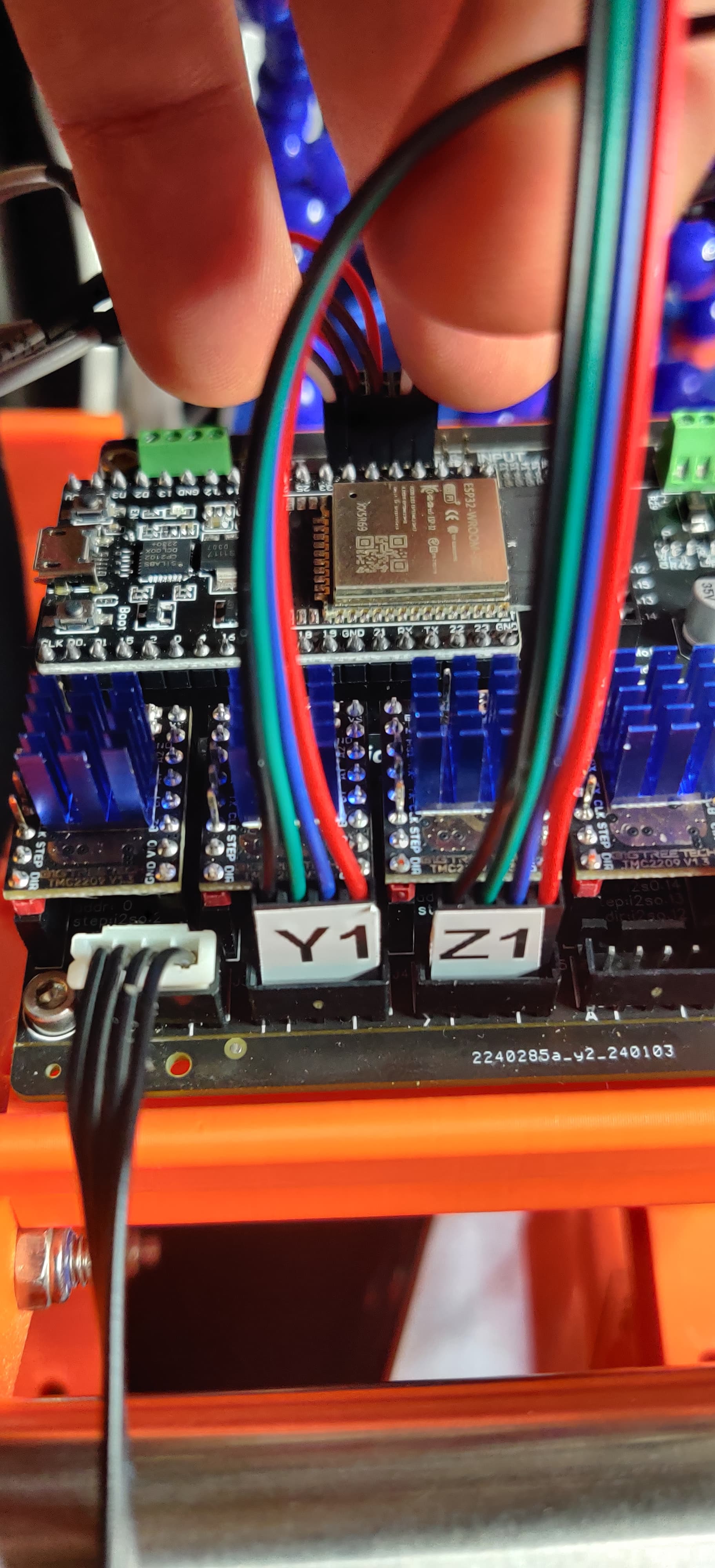
I’m not sure if I’m looking at this photo correctly or not.

If those are normal Molex connectors, please note that to me it looks like the JST plastic shields are still on in place.

Leaving the plastic shields in place, normally results in loose stepper motor connections.

The instructions state to remove the shields to avoid loose connections. Others have replaced the Molex with JST connectors.

I’m not completely sure I’m seeing this correctly or not, as with your troubleshooting to figure out the blue/green swap, you saw how nice and tight the JST connector was. And maybe might have noticed how loose the Molex was compared to the JST? If yours are nice and tight, or you’ve already pulled the shields, my apologies.

“Depending on what wires you are plugging in you can take them off the end stops and stepper ports. Even after doing this you should always constrain your wires directly after the connection to the board to prevent them from wiggling loose.”

!Shields off

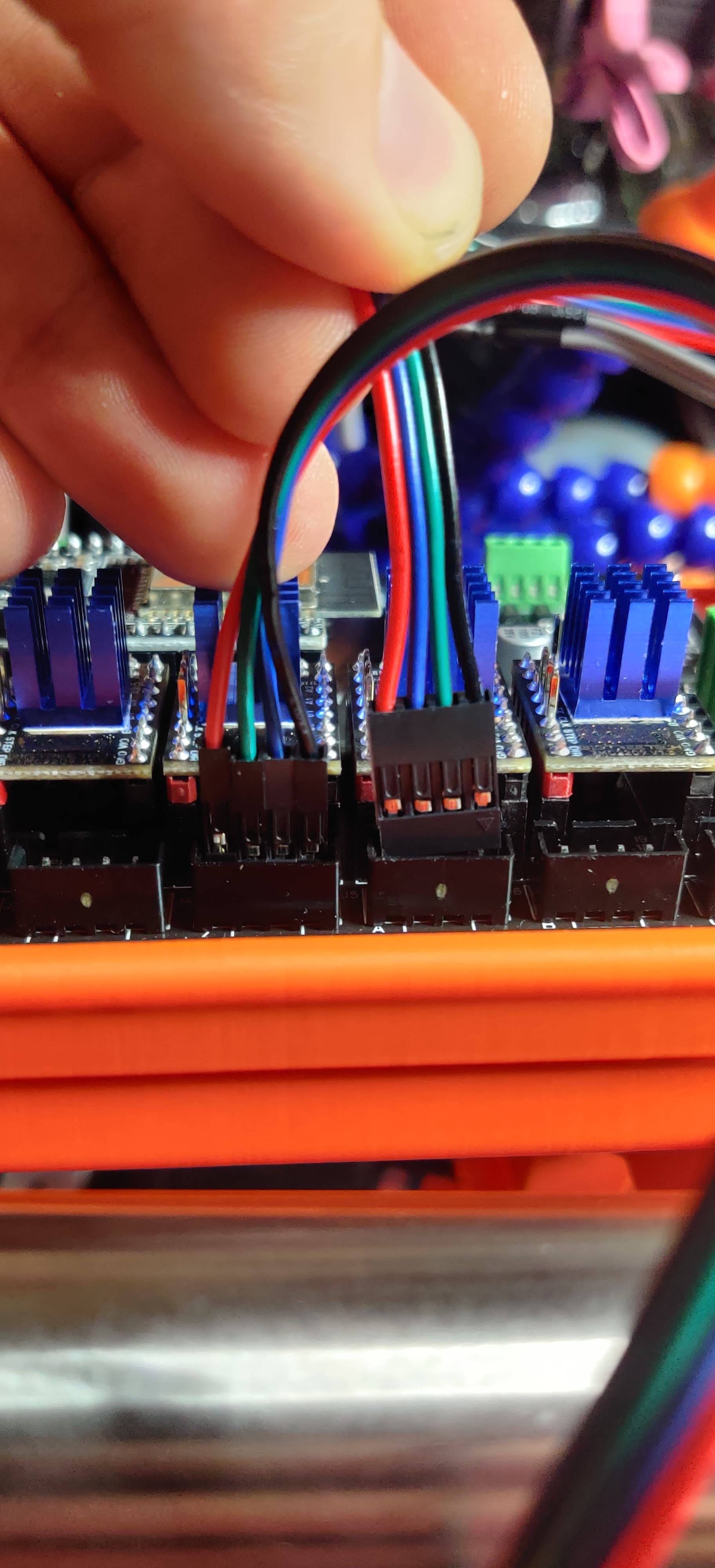
I did put cables from JST-to-Dupont cables between the board and the cable that comes from the stepper. This photo was to demonstrate what was going on. If you look closely you can see the left one has 4 separate 1p headers, the right one is 1 4p header. Its a lot easier to test with 4 dupont headers than it is with a JST having to repin them constantly.

have you sovle the problem?

I find this one is similar to yours: