I have those same magnets holding a face on my snake enclosure, they are strong!
4 Likes
Whose face?
2 Likes
Its more of a wood face to access the lower enclosure, to be able to access the lights and heater.
Are the printed parts available yet for the LR4 as the links to printables are thingverse are failing. I have been waiting for the LR4 release to start building the LR CNC and to get started I would like to fire off a few prints to see how well they work with various tubing that is available here in Ireland. The variety of tubing available once you go over 25mm is substantially reduced so I need to experiment with 30/32mm tubing to find a viable option. Thanks!
1 Like
They have not been released just yet but should be in the coming days.
2 Likes
It seems they’re available now!
4 Likes
Doug - I remember somewhere you had posted how to adjust a table that already has super struts so that it can handle a LR4, but I can’t find that post. Also - do you know how to back calculate so I can have it as wide as possible with the current superstrut based table? I don’t think Ryan has had time to post an engineering drawing so we can see the measurements? (I can’t imagine why? ![]() )
)
I’m just looking to back calculate from the table I have. Any adjustments you’re dealing with may with finalizing the beam length. Specifically, where do the new wheels hit the superstrut relative to the dimensions on the calculator?
Well, I don’t exactly remember making a post like that, but remembering is tricky. I can say that, because the LR4 is a bit more compact and better (more efficient on protecting cuttable area) for my full-size LR3 that’s being upgraded to LR4 even as we speak, my current working plan is to get the non-rail side’s YZ plate to ride “centered” dead over the metal strut on that side, which represents moving it from where it used to ride on the very edge, nearly off the strut, and based on my calculations, it means I can maintain the same cuttable area, while cutting my new steel tubes at 1398.06mm (55.04").
For comparison regarding the above, my LR3 steel tubes were cut at 1,435mm. Again, new ones are being cut at 1398mm.
This is based on me constructing a virtual model of the LR4 based on my existing table’s width and layout, and using the STLs to populate the model.
PS: the plan involves some printed “table extenders” that will need to be tested, which will insert into the ends of the metal struts.
2 Likes
Note: the plan I referred to above, actually loses a bit of cut area on the X-min side, but gains some on the X-max side, and I would need to move my spoil board toward the X-max side by about 14.3 mm to keep as much cuttable area as I have now, accessible in the new.
Trying to keep the non-rail side’s YZ plate riding on the edge like now, would technically be doable, and would mean I gain new usable area, but it would also extend the printed “table extenders” on that side, and the further they stick out, the more risk there is of issues of flex and creep.
For the new LR4 calculator, I’m targeting cuttable area of 1231.9 mm (48.5") and it says the strut for that should be 1398 mm, which seems to correspond fairly well to the 1398.06mm I indicated above.
If the cuttable area is calculating from a “point” at the center of the bit, then you get to add the tool diameter on, half of that (radius) on the X-min side and half at the X-max side. If I am using a 1/4" bit, I could cut 48.75". For surfacing a spoil board, if using a .75" bit, I could cover 49.25" – which, if centered correctly, is more than enough for a 49" sheet of MDF.
1 Like
Care to post a screenshot?
How is this plan better than say making “wings” from MDF that simply sit atop the unistrut and provide both a mounting surface for +X rail and a rolling surface for -X? An upside of that approach would be you now have the beginnings of a “boost table” where you can add max Z just by stacking plates.
One of the lessons / improvements from LR4 is managing how far things (Don’t) protrude below the cutting bit as the lever arm you create this way is actually detrimental to machine performance.
1 Like
I had started thinking earlier this evening about both that possibility (MDF runners on the metal struts) and also the possibility of making the wing extensions be aluminum bolted to the metal struts. Before all this is done, I may well do one or the other, instead of the printed table extenders.
The only X length I’ve already cut, are 5.x mm thick hardboard JPlates. If I need to change the plan, and want to go a bit wider, the waste of those already cut JPlates won’t be a great loss. They are not yet laser engraved, and the steel EMT are not yet cut!
I went through a lot of planning delay at the start of the beta test process, before I got the confidence to cut steel and JPlates. It’s who I am, and has a lot to do with how I was raised and how frugal I am. I will get there. And after I get there, I may leave and go somewhere else, but eventually I’d get there too! LOL
2 Likes
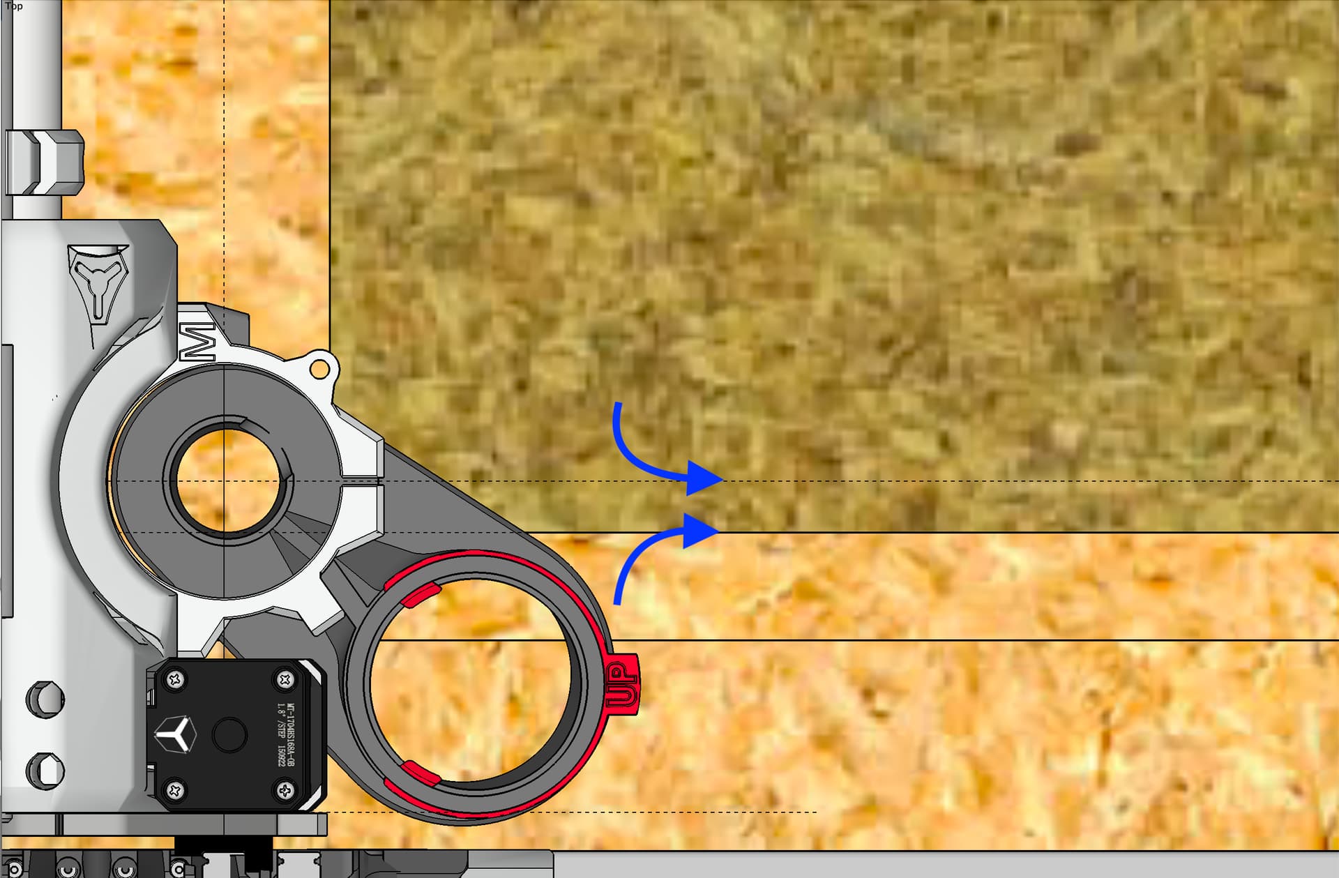
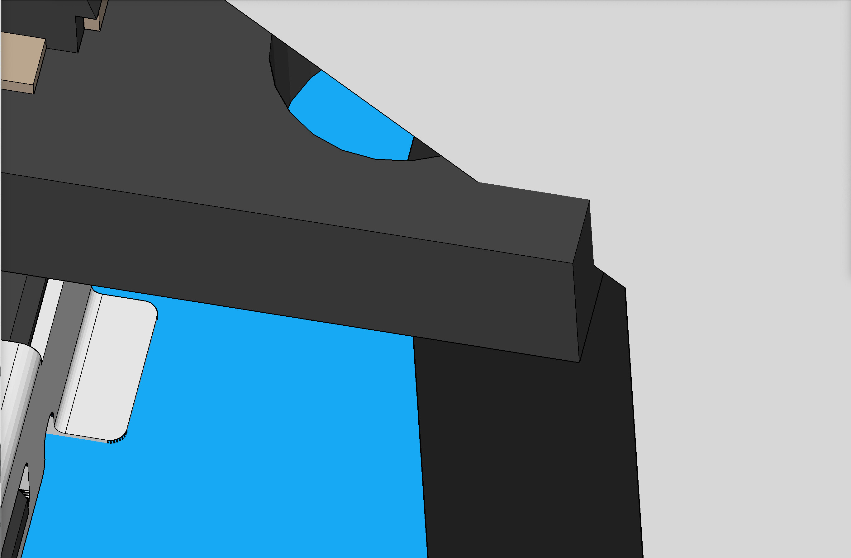
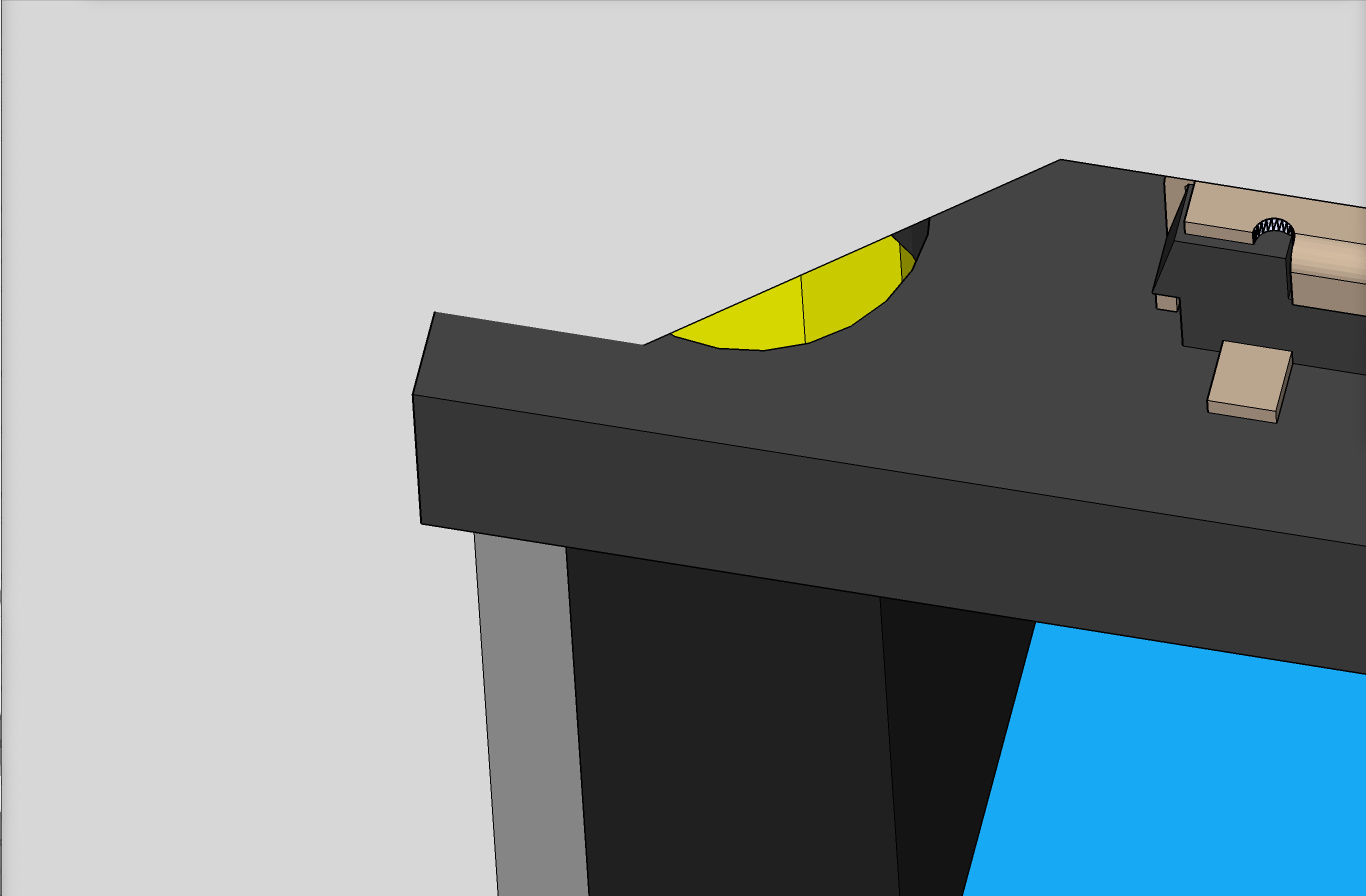
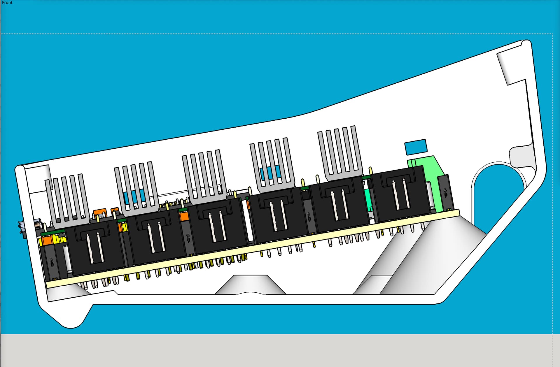
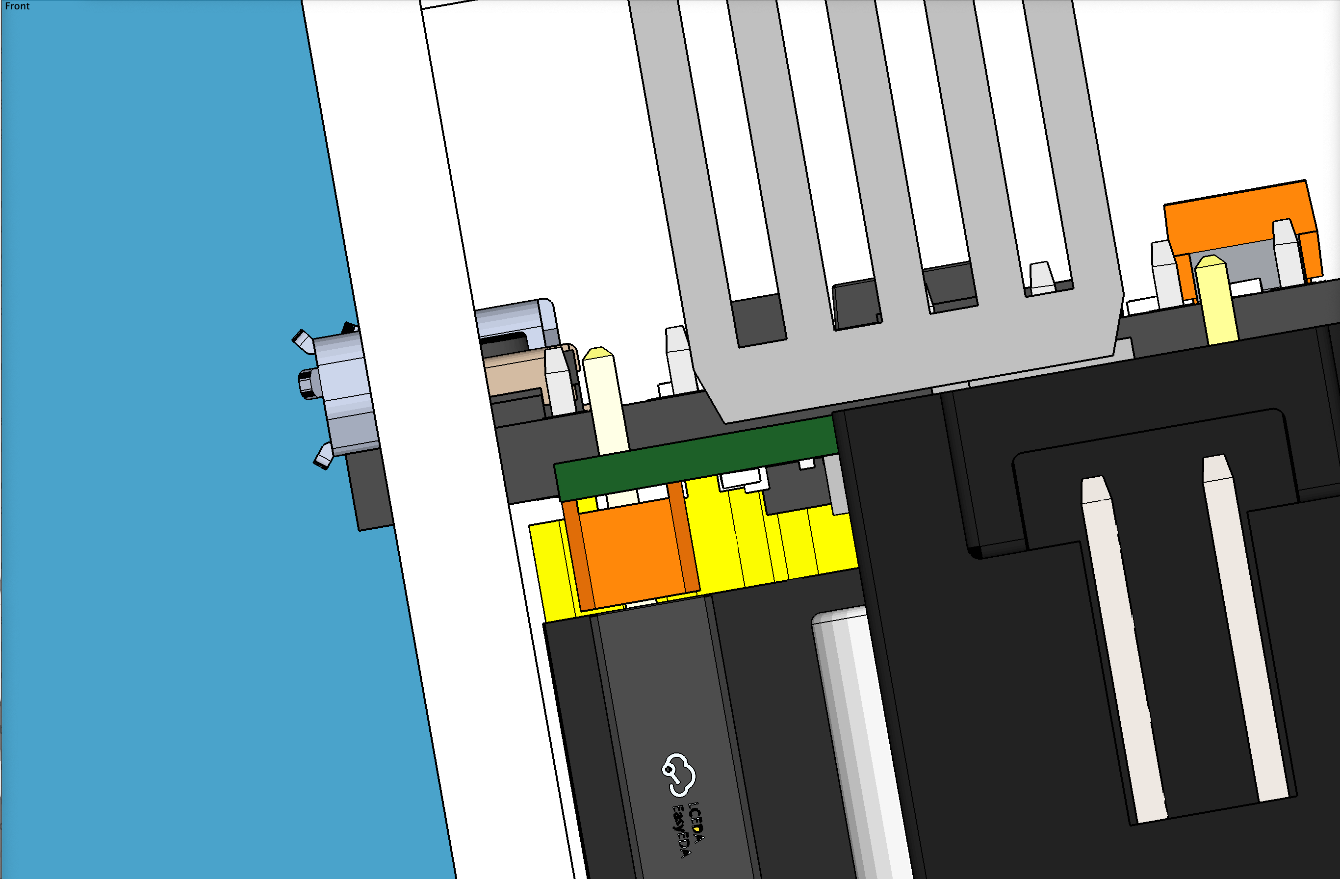
In this screen shot, some aspects of the working model are not yet realistic, and don’t need to be since I know what’s up. For instance, the old table is shown, which was made before the torsion box. It does show the metal struts, and the width of the old table matches the width of the new. The old table had metal struts attached at the same width apart as on the new torsion box table.
This is showing the non rail side. If my model is not too far off, the blue arrows indicate the current edge of my spoil board, as well as a guideline about 14.3 mm away from it, which is where I’d need to move the edge of the spoil board to, to maintain and center my cuttable area.
1 Like
I just had a thought based on the MDF runners attached to top of metal struts. If I put two strips of 3/4" MDF side by side, and used piano hinge to attach them to each other, perhaps the “open” version would be regular table, while the “closed” version would be a 3/4" drop table. The crucial keys would be the hinge allowing them to “close” against each other perfectly, and them both having some type of quick release version of the belt tensioners. Because I have a gap between the spoil board area of the torsion box and the metal struts, the MDF strip being “opened” could open toward the inside of the table, not the outside.
1 Like
I guess I’d need to understand how this would be implemented on the rail side. But this would allow me to use a thicker spoilboard which might help. I already have the drop table section, although I generally only use it for laser work.
I could slap some MDF on the rails for the short term. Or just remove them and replace with MDF rails. Lots of possibilities.
1 Like
I did not get that far in the thought. LOL. squirel!
1 Like
LR4 models have been published for over 24hrs already. Guessing someone(s) made a Kinematic mount already based on the LR3 version? ![]()
5 Likes
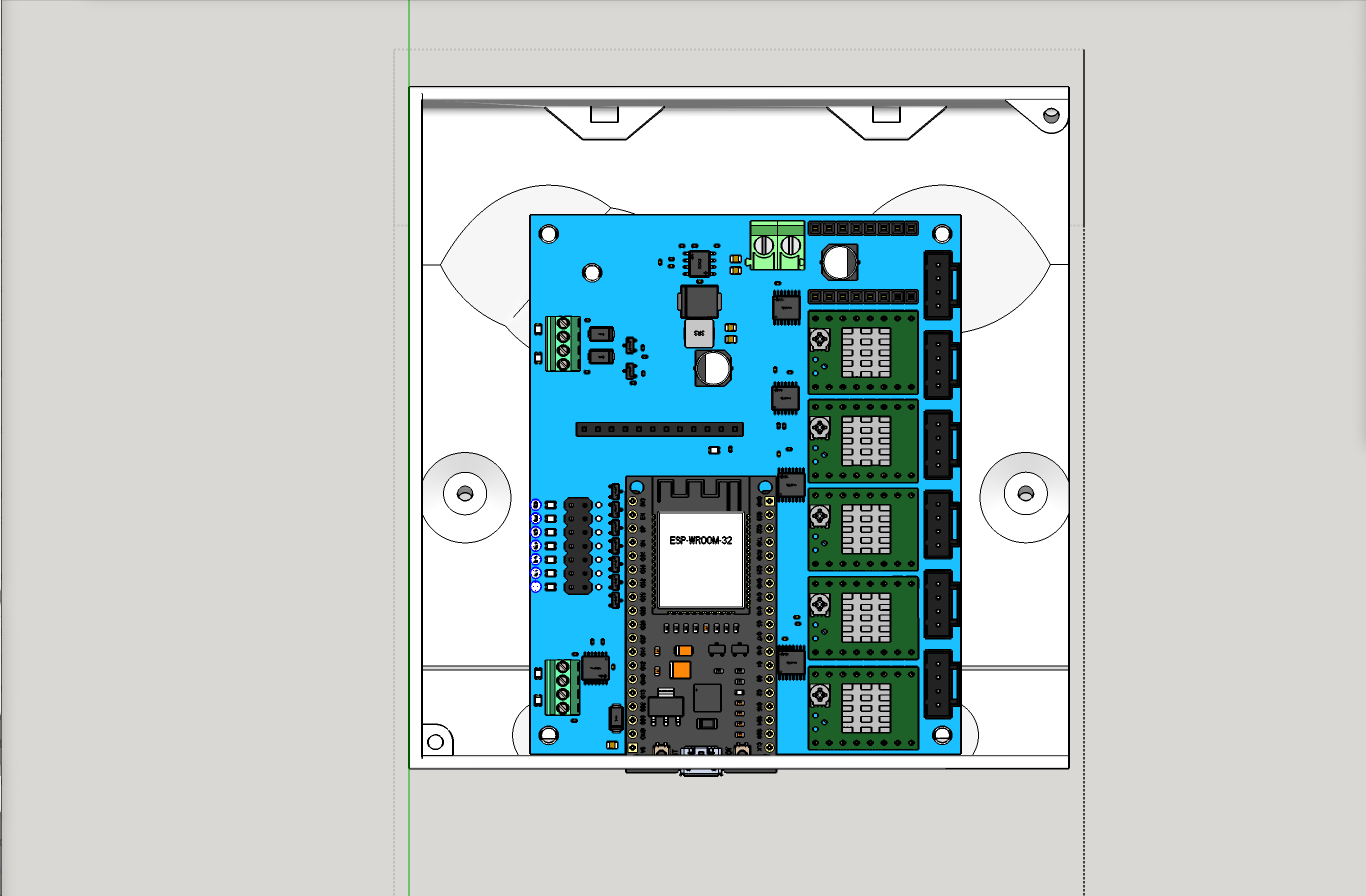
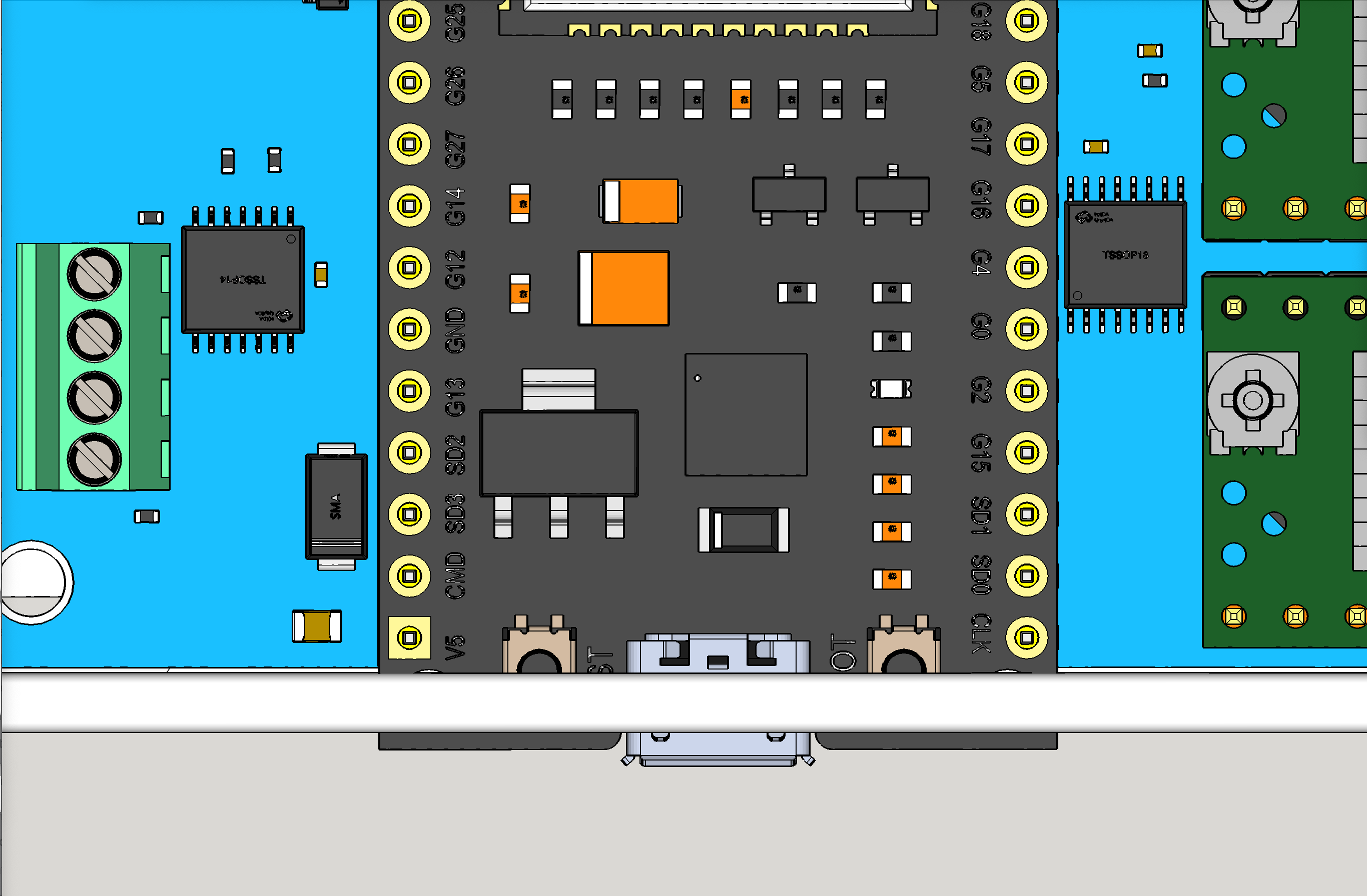
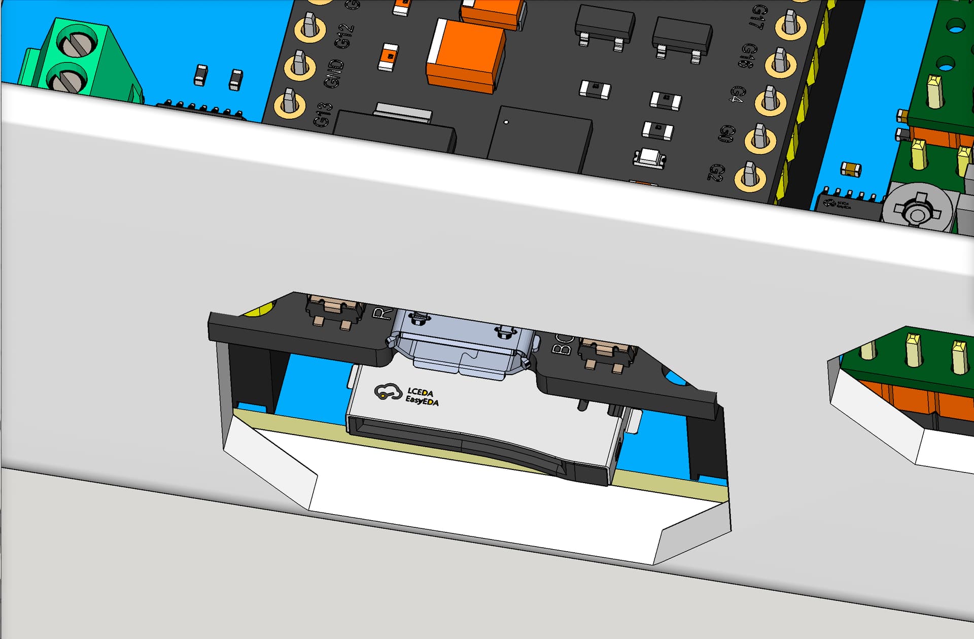
@vicious1 Quick question on Jackpot case (V2). I imported the mesh to have for possible tweaks, and I added your Jackpot board model. I lined it up, and it shows a bit of a collision where the USB port is. Is the model right?
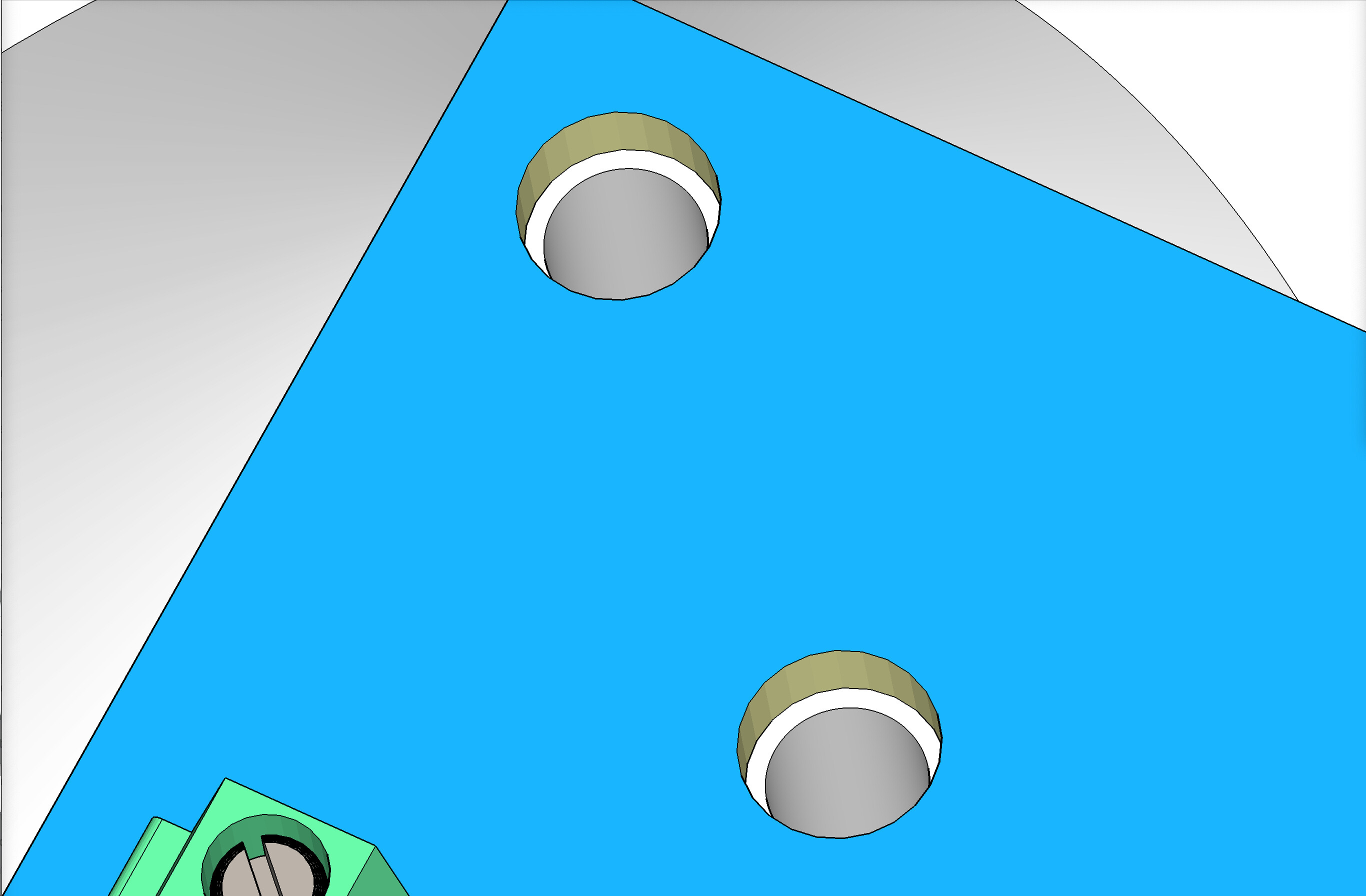
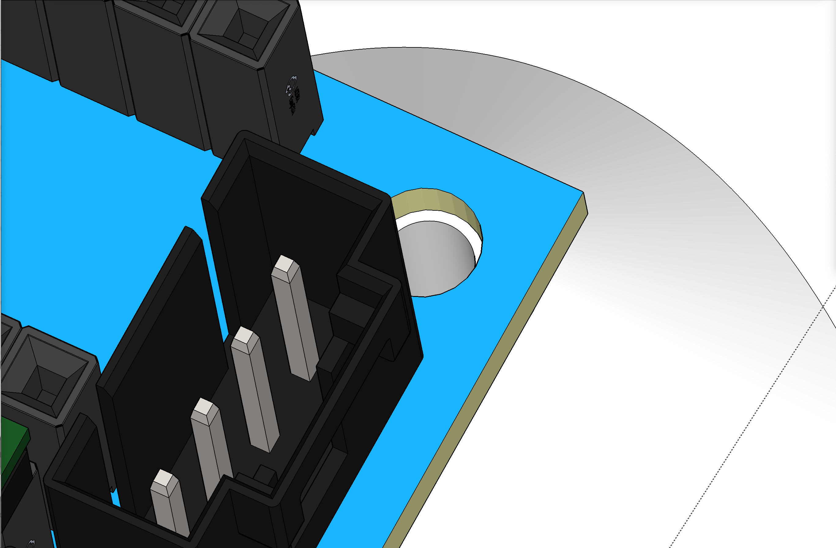
1 Like
I am using his box right now and I don’t have any collision with the esp32
2 Likes
OK wont worry then.
1 Like