Starting with MKS DLC32

Good evening,

It’s for my DIY CNC Plotter/Laser project… My MKS DLC32 board is currently being delivered (according to the tracking, it will arrive in a week). I still have quite a few questions about this board that I’ve decided, after some consideration, to use for my CNC project.

I’ll start with a question about power supply. I plan to use 12V for the entire setup. Is it more advantageous to use a single power supply for the board, the few 12V fans, and the Laser module, or should I use separate power supplies for the Laser and the board? Also, what power rating should I use?

1 Like

If you only beed the single voltage, one PSU should be OK, IMO. As a rule of thumb, I would budget 1A per motor, plus whatever your laser module says that it needs. If you’re going to add several fans, LED lights or other load to the power, budget for that, too.

So my CoreXY laser needed 2A for the laser, and had 2 motors, so the 6A supply I had was plenty. My next build will use 3 motors, and needs 4A fir the laser. The 6A supply is probably still adequate, but I will use a separate 24V supply for the board/motirs, and the 6A 12V supply for just the laser, and maybe a fan.

2 Likes

The MKS DLC32 card, let’s say 1A… The motors that I plan to use consume about 1A per motor, so a total of 2A … The fans (three of them) consume 1.5A max … The laser module , 4A … I add for safety, 1A … Total = 9A. So, normally, a 10A power supply should be sufficient.

My idea is to use a single, simpler 12V power supply. But if it’s more advantageous to power the motors at 24V, I can adapt and use two power supplies.

Really, what is the advantage?

1 Like

1.5A for fans? Wow, those are strong fans… I think my 120mm fans take about 200mA.

The advantage to 24V for the motors is top speed. 12V will handle the vast majority of what you will want, if not everything. If you vave an adequate 12V supply, just use that, and think about upgrading if you have a problem that higher voltage will solve.

I say that, but tend to run dual supplies on my machines…

1 Like

:laughing:
I thought 0.5A per fan… quite a generous measurement! :grin:

Apparently, 24V is more ‘robust,’ so I’m switching to 24V.

No problem using 24V with the MKS DLC32 board.
No problem using 24V with the motors I have (NEMA 17HS2408… and maybe a NEMA 23HS8430 on the Y-axis if I find the NEMA 17 is a bit light).
No problem using 24V with my laser module LT-80W-AA-PRO.
The fans are 12V… well, I’m trying to find a solution.

Is that good?

1 Like

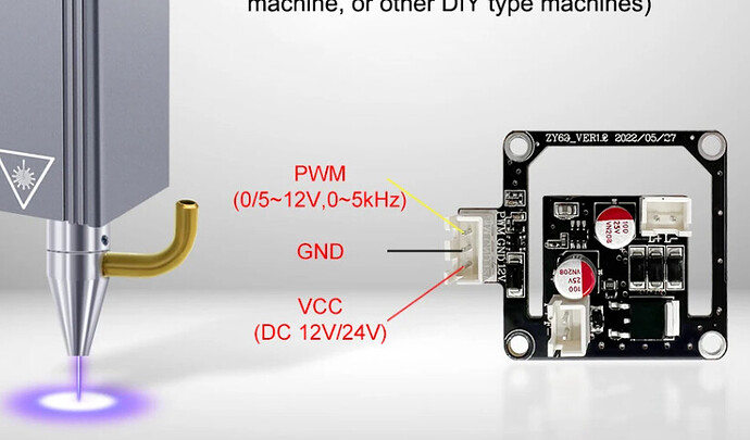
Question: If I power my MKS DLC32 board with 24V, does it have any impact on the PWM output, which is normally at 5V/12V

1 Like

I use a couple of cheap step-down buck converters for my printers to supply 12VDC for LEDs and some fans. They cost about $5 for ones that can supply 3A or so from the 24V main supply. Not enough for a laser (Mine want 12V 4A) and it’s cheaper just to buy another AC supply for those.

They do the job perfectly well for my LEDs as well. I also have a PWM DC motor controller that I use for the LEDs to act as a dimmer switch, which works great. Most of the time I want on/off, but sometimes a little less bright is better.

Even though I use 24V, I don’t think it really makes a difference for CNC machines. For 3D printers, the 24V makes much higher power heaters and heated beds, or at least much higher power devices are available. For CNC machines, it seems to be much less so. (Though watching my LR3 scoot along at 12000mm/min makes me smile, even if the only thing it does at those speeds are rapid non-cut moves.) I don’t see any harm in using 24V except that fans are more expensive (Mitigated if you use a 12V step-down) It certainly does no harm, which is why V1 started selling 24V power supplies.

Most of the PWM outputs are at the regulated 5V, which should be fine. The wiki article on the DLC32 says that the TTL output is 5V switched, which is perfect. In fact it looks like you could just use the 3 pin output there to deliver Vin, Ground and TTL at the same header.

1 Like

Still awaiting the arrival of my MKS DLC32, which is currently stuck at customs for reasons unknown.

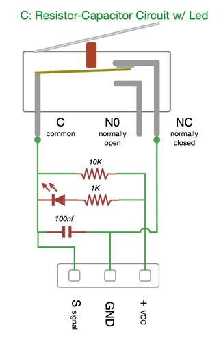
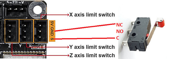
Meanwhile, my focus is on the limit switches. In my initial design, I intended to use a simple switch with two wires, a configuration I am confident will function correctly. However, the MKS DLC32 board is designed to accept limit switch modules with three wires, as per my readings.

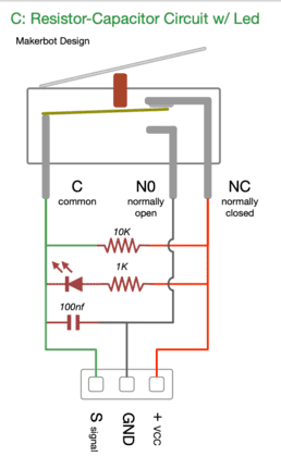
Since I hadn’t planned to accommodate modules, I am considering DIY my own. I came across a diagram, but I’m uncertain of its accuracy.

image

or

image

Additionally, I found this site claiming that the limit switches in the module do not work correctly. According to their experience, they had to switch to the 2-wire mode for proper functionality.

I’m seeking more information from anyone who can shed light on this matter. I would like to avoid unnecessary modifications to my design.

THANKS.

Another question, please, regarding the configuration of limit switches. I had initially planned to incorporate an emergency stop button, but I am unable to locate a dedicated connector for it. What should be my course of action?

THANKS.

still waiting any help please … :roll_eyes:

Hello. I’ll see what I can do to help you, though the DLC32 isn’t one of the core boards used by the v1 community. (I personally have seen a DLC32, although it is because I helped a friend with a machine and my first step was replacing their DLC32 with a Jackpot board)

There looks to be a reasonably good start of documentation for the DLC32 here:

From that, I note a decent overview connection diagram:

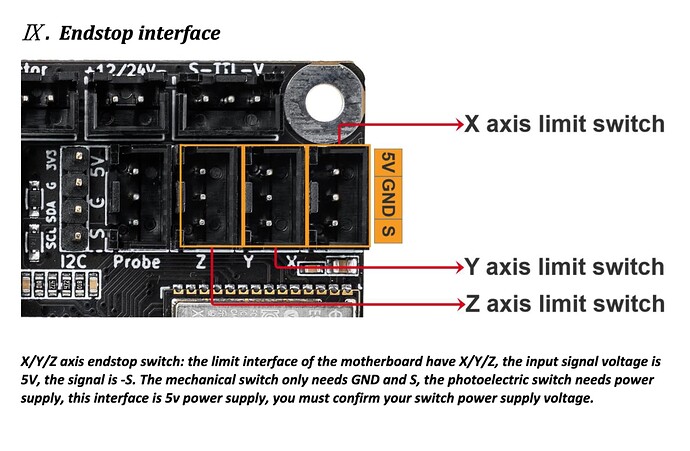
I also see this note in the section on endstop wiring:

Based on the note shown above, I wouldn’t bother with an optical endstop module and would use a mechanical switch only, using signal and ground. One reason for this is those +5v pins on boards are a great way to fry boards when misconnected or shorted.

I’d say your initial design was the better choice. I wouldn’t mess with trying to get the optical modules correct. I’ve used them in other places (3D printers), and while they can work well, getting a system correctly interfaced with them can be tricky for DIY. You also have the persistent possibility of killing your controller with a mishandling of the endstop modules and wiring.

This is a big discussion. Here’s a bit of input from me for you to consider.

First, in looking over the board wiring diagram above, there does not appear to be provisions on the DLC32 to hook up a door or pause switch to it. That really isn’t an E-Stop, but may times people desire such functionality as an intermediate response. It’s a significant limitation of the DLC32.

Next, in my opinion, if you’re having an emergency there is only one proper response- Kill all power to the machine. To do this, you should have an external switch somewhere on your machine that kills all AC power to all power supplies- the DLC input power as well as the laser module power if you use a separate laser power supply.

2 Likes

I appreciate your response - it’s clear and reassuring. I’ve decided to stick with my original switch configuration.


is that correct?

I have an on/off switch that I can use as an emergency button if necessary.

Thank you!

1 Like

It looks correct to me.

It is better to wire the switches NC, so that is what I would do. Make sure your configuration is for NC endstops, which should be the default.

That seems sensible to me.

1 Like

Received MKS DLC32 board today (had to go through customs and endure an interrogation to get it… well, miserable!)

I’m now switching to programming mode.

I’m leaning towards the FluidNC solution. I’m trying to finalize my wiring; I’ll post it later. I’m doing some readings to understand the configuration procedure a bit.

I would appreciate your assistance later for the ‘correct’ installation of everything on the board.

Thank you.

1 Like

FluidNC is a really nice motion control environment, and would be a good choice.

There’s always plenty of user community support here in the forums, and I’m sure you’ll find plenty of help and encouragement as you make progress with your build.

1 Like

my setup :

For installing the firmware on the board and as recommended on the FluidNC installation page, I’m using the web installer. However, a simple test with just the USB cable yields no results. The board isn’t even recognized by my PC. Apparently, it needs to be powered with at least 12V (isn’t that right?).

I’m focusing on the firmware. I’ve downloaded the latest version (v3.7.12). Now, do I need to make modifications to this firmware to make it compatible with my setup?

Thank you.

Edit:

  • It needs a power source other than USB.
  • Adapting it to my configuration is done at the configuration file level.

I’ve done some reading on the wiki, but it’s complicated!!! :roll_eyes:

Good…

The FluidNC firmware installation is successful… OK

The web interface is working flawlessly… OK

However, the configuration file creation is problematic… NO

Apparently, I need to create my own file or modify an existing one. There is also a feature in the web interface called “Config Items.” I wonder if I can make the necessary modifications directly through this interface.

if anyone can help me in creating this configuration file… because I’m a bit lost there

1 Like

There appears to be an example configuration in the FluidNC config repository. That’s probably a good starting point for you to modify as you build out your machine.

To help you modify it will require that you supply the details of your build. I’d recommend that wherever possible you follow this config as a template. (In other words, hook everything up as the config file has them called out, and then it should work with minimal modifications.

2 Likes

Alright, I consider this configuration as a starting point. The first modification, which is crucial, involves incorporating servo control through the probe port. As this board is tasked with overseeing two outputs, namely the Laser and servo, a friend recommended adding these lines. I would appreciate hearing your opinion on this.

besc:
pwm_hz: 50
output_pin: gpio.22
enable_pin: NO_PIN
direction_pin: NO_PIN
disable_with_s0: false
s0_with_disable: true
spinup_ms: 20
spindown_ms: 20
tool_num: 100
speed_map: 0=0.000% 100=100.000%
min_pulse_us: 900
max_pulse_us: 2200

I’d like to comprehend them line by line. Is there some sort of wiki or resource available for these commands that provides clear and detailed explanations?

The FluidNC wiki has pretty thorough documentation on the configuration file.

1 Like

Okay, I’m using the file MKS_DLC32_v21_laser.yaml as a reference to create my own file.

1- I make a copy: MKS_DLC328v21_Laser_Plotter.yaml
2- I try to make the necessary modifications block by block
a)

board: MKS-DLC32 V2.1
name: eSloch Laser_Plotter
meta: eSloch 17/01/2024

Doesn’t it look nicer like this?

b)

kinematics:
Cartesian:

I don’t modify … apparently, that’s my situation.

c)

stepping:
engine: I2S_STATIC
idle_ms: 255
pulse_us: 4
dir_delay_us: 1
disable_delay_us: 0

I think the only thing to change is the ‘idle_ms.’ If I understood correctly, a value of 255 implies that the motors are always powered, which is better for precision in movements.

I don’t know about the others. I believe they are fine and shouldn’t be modified, even if I don’t fully understand them.

d) The serious stuff begins here:

axes:
shared_stepper_disable_pin: I2SO.0
x:
steps_per_mm: 100
max_rate_mm_per_min: 16000
acceleration_mm_per_sec2: 1500
max_travel_mm: 895
soft_limits: true
homing:
cycle: 0
positive_direction: false
mpos_mm: 0.000
feed_mm_per_min: 300.000
seek_mm_per_min: 8000.000
settle_ms: 500
seek_scaler: 1.100
feed_scaler: 1.100

motor0:
  limit_neg_pin: gpio.36:low
  hard_limits: false
  pulloff_mm: 2.000
  stepstick:
    step_pin: I2SO.1
    direction_pin: I2SO.2:low

So, the “steps_per_mm”… how should I define it? … Also, the “max_rate_mm_per_min” and “acceleration_mm_per_sec2”?
I’ll calculate the “max_travel_mm” precisely once I finish the CNC design (in progress, almost done).

For “soft_limits,” I set it to “true” since I only have two mechanical limits on my CNC. I think it’s interesting.

Now, the “homing” section: is a cycle of 0 correct? What about the other parameters? Are these values correct to start with, or could they potentially harm my machine?

In the “motor0” section, for “limit_neg_pin,” is it “gpio.36” or “gpio.36:low”? And for “hard_limits,” is it false or true?

Alright, my head is already aching. I need to understand this in more detail.

:dizzy_face: :dizzy_face: :dizzy_face:

I noticed in some config files there’s an indication of the stepper used. In my case, it’s TMC2208. Should I specify this somewhere in this section?