Any tips on the best method to make sure the workpiece is square to the machine? If I want to engrave words on a square piece, I need to be sure the writing is not running slightly slanted.
The surest way is to machine the perimeter of your workpiece in the same setup as your engraving (in other words, the material clamped and doesnt move between perimeter and engrave, the motors remain powered, and the machine coordinates are not homed in between cutting operations).
Alternatively, you can machine a corner into a sacrificial workpiece, then mount the engraved material to it. This still maintains that you dont power off or re-home the machine.
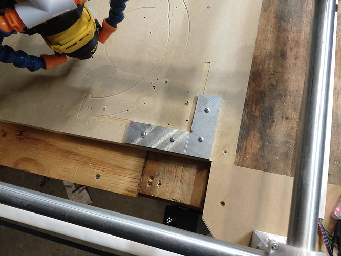
More permanently, you can mount a metallic corner on your machine, and bump it with G28 in X and Y. If the metallic corner is square to your gantry, then any piece you place in the corner will share origin and orientation with the corner. This is what I did. To ensure the corner is square to the machine, I mounted the aluminum plates, then shaved them with the CNC itself.
My results are pretty good, not perfect repeatability, but probably closer than the eye can detect if I set up the job right. I am noticing that I need to start using a solid pin in the spindle to bump the plates, the tip geometry of the bit is causing inaccuracies in my X-Y homing. Also, IF i trusted the plane of my table, I could even home Z to these plates and program with a 1/4" z-offset in my work (I do NOT trust the plane of my table, so I still use the tiny touchplate, haha)
1 Like
I just move the tool so it is touching (or right above) on place on the edge, then jog 100mm over and turn the workpiece so it is touching again.
After making a few through cuts, the spoil board has a bunch of square lines that help give me a good initial guess.
1 Like
Thats the quickest and easiest method I have adopted as well. Seems to work well enough so I will continue with that. Maybe one day ill get around to something more sophisticated like the method Nicholas uses.
I usually do the same thing and that works good enough for most things. For operations, like cutting 2 sides of an aluminum part clamped in a vice, eyeballing it is too sloppy. For those situations I use a probing script, and adjust the clamping until the error is zero (or otherwise within spec).
Here is an example of a 2-point Y probing script I use to align my vice jaw:
(Vise Hard Jaw Y alignment macro)
(Probes vise hard jaw ~5mm in from left and right edges. When finished)
(the probe parks near the starting position, with the Ywcs equal to the)
(total Y alignment error measured between the 2 points.)
(1- Install probe, and connect probe & vise clips)
(2- Open up vise and jog the probe in front of left hard jaw corner:)
( Z = -10mm below top of hard jaw)
( Y = 5-15mm away from touching jaw)
( X = 5mm in from left side of jaw)
(3- Run the script, and read Y when finished)
(4- Nudge vise handle left if error is +, right if error is -.)
(5- Repeat 3&4 until vise base is tightened with zero error or otherwise within spec)
(6- Remove probe, install cutter bit, setup/zero your WCS, etc.)
G38.2 Y20 F100
G91
G0Y-3
G10 P0 L20 X0 Y0 Z-10.000
G91 G0 X65
G38.2 Y20 F100
G91 G0 Y-3
G91 G0 X-65
G90
This aligns 65mm wide along Y, but the general idea can be modified for other needs. It allows you to quickly and accurately check clamp adjustments. You just hit the run button again to get the error after bumping your clamps… rinse and repeat.
Recently I read in a post that one of you all set your Z home to be the surface of your table/spoil board. If you do that how does Estlcam know that? Been a while since I’ve used it so I don’t remember the settings off the top of my head.
There is a setting for where to put the origin.
1 Like
Use a vbit to cut a grid into the spoil board and line up on that.
Otherwise, I typically use the method Jeff mentioned.