So I had no idea when I built my MPCNC how to secure anything to the bed. As a result my first base is pretty messed up now. But of course my machine is attached to it. So I am going to have to take it apart and put it back together on a new, better thought out base.
Anyway, I had a hard time squaring the legs when I started this project. And I think I’d like the ability to move bases more often, or to change the size of my base. So I ended up designing a part to address both problems.
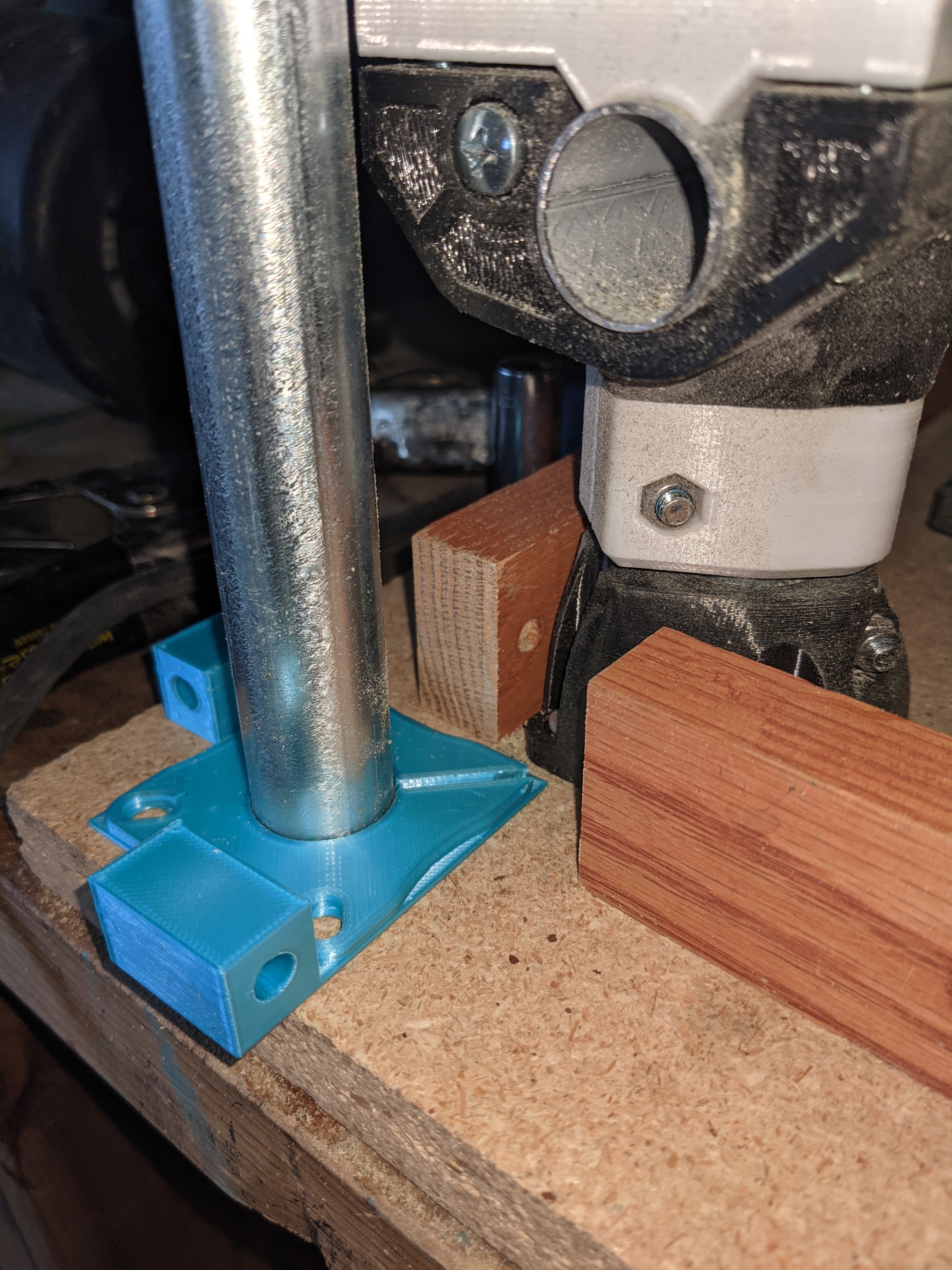
The below shows an early prototype of a piece that is meant to go under all four legs. The conduit goes through it and the leg. Threaded rod will go through the holes on the edges, forming a square. I plan to use locknuts (4 per rod, or 2 per foot per rod) to hold them in place. I should be able to measure everything accurately and ensure nothing can move this way.
Anyway, before I go too far down this path I thought I’d post here for everyone’s thoughts. Is it dumb and there’s some much better way? Are there things I could do to improve it?
[Edit: if it isn’t obvious I printed only the first 1mm of a foot for that test. It’s in the same blue color so it is hard to tell. the foot sits on top of the new piece, and the conduit goes through both, keeping them aligned.]
Thanks,
I see a lot of beds designed like yours where stock is mounted to the base, but typically there are a couple cuts through the top layer that allow the center portion to be replaced while keeping the legs mounted. You could use a circular saw and modify your existing setup this way. As for your design, it only makes sense to me if you plan on adjusting the size of your rig as mentioned. The original squaring, while it can be tedious, is only done once for a given size. The one downside I see is that you will not be able to handle stock that extends beyond the edge of your base board. Note there are g-codes that allow you to adjust for skew to a certain extent.
As with any modification to the MPCNC, if you do this, I love to hear how it worked out for you.
Interesting. My stock is almost always 1 1/2 x 6" or 1 1/2x10", which is why I’m adjusting the size and why I didn’t even think about stock that extends beyond the edge (although the threaded rods could be removed later, I suppose). I’ve got a bunch of 3d printed mounts specific to this stock that I want to be able to work with more easily and accurately. I’m trying to get to the point where I can do two sided work, but it seems to me that is going to require a level of precision I haven’t achieved yet.
I had no idea what I was doing when I built it, and now realize it’s bigger than I need. I don’t have a lot of space so it would be nice to make it smaller. And in any event I need to redo the base, which is full of holes and keyhole channels of dubious quality, since I also didn’t realize bolting it onto a square of MDF was a bad idea.
I’ve already rebuilt a bunch of it (for example, it turns out my original conduit was slightly small in diameter, contributing to z axis problems). I just view that as part of the process–gradually making the machine better for my purposes. And part of the fun.
I had a four hour drive today, and I spent part of my drive time thinking about the problem you are trying to solve and your solution. In my head, you have a couple of issues. The first is that your solution ensures that each side is the same length, but it does not mean it is square. It could be a parallelogram. What you really want is something that allows you to both measure and adjust the diagonals.
The second problem is that once the holes for the screws are drilled, smallish adjustments become difficult/impossible without moving all four legs by 3/16" or so. A screw is going to want to seek the same hole, and therefore will pull the corners back to the position where the holes were drilled. You probably need to move all the legs at least the diameter of the shank of the screws you are using to hold down the legs. This is not a deal breaker, but this just means you might as well remove the threaded rod once you have the feet holes drilled since you won’t be making incremental adjustments.
I know there are STLs on Thingiverse to help solve the squareness problem. I’ve not used any of them, so I cannot give you any feedback. Do a search on Thingiverse for “MPCNC Square.” Here is one such solution as an example.
When I built my Primo, I printed a couple of layers of a foot, and used that 3D print as a template. It allowed my to precisely draw the foot outlines and predrill all the holes before attaching the feet. My diagonals were spot on.
I’ve been thinking of ideas like this. I’m going to be rebuilding my Primo to be smaller once my LowRider is up and running, since I want to be able to deal with more difficult materials.
My idea is based around something like Superstrut.
The origin corner would be permanently mounted on top of a 1 5/8" block, with 2 lengths of superstrut to either direction. These would be carefully squared to ensure a perfect 90° corner. The 2 adjacent corners would then be mounted to pieces fit to the superstrut structure. They’d be able to slide, but have a lock to them. This is basically a block cut at a 45° angle, so that when a bolt through them is tightened, it tries to widen, thereby locking the corner in place.
The final corner would also have a 1 5/8" block under it, and could be held in place with the structure tube, placed so that the rails are parallel to the known square ones. This way, any size for the machine is guaranteed square, with relative ease of setting the size of the X and Y axes.
Well, that’s about how far I got before I realized that I still need to set the table under the whole thing, so I might as well just make it the size of the table I eventually decide on. There’s an additional complication with my Primo too in how I chose to elevate the drag chains. I am actually very happy with that part of the design, so I plan to keep it that way. I’ll just cut my pieces of slotted angle shorter when I shorten the machine.
Huh. I hadn’t thought about the parallelogram. Although the idea is that the part keeps the threaded rods at a right angle. I guess I have no idea yet how much flex could be an issue. I did print it pretty thin.
I agree re: the screws and removing the threads. Though my thought is that by keeping them on I might be able to easily replace the base MDF w/o losing my square. I have a feeling my second base design won’t be my last.
I had originally been thinking of designing an interlocking, modular base system kind of like those interlocking foam floor squares. But whenever I’ve tried that sort of design in the past w/ 3d prints the tolerances haven’t been great.
So I’m finally getting around to rebuilding the base. The pieces I originally build are useful but ultimately probably not worth it. I struggled with accurately measuring diagonals on some conduit 100mm above the base and ended up printing some caps with references on them.
Hopefully by the end of the day I’ll have a new base that is square AF