Spoilboard surfacing approach

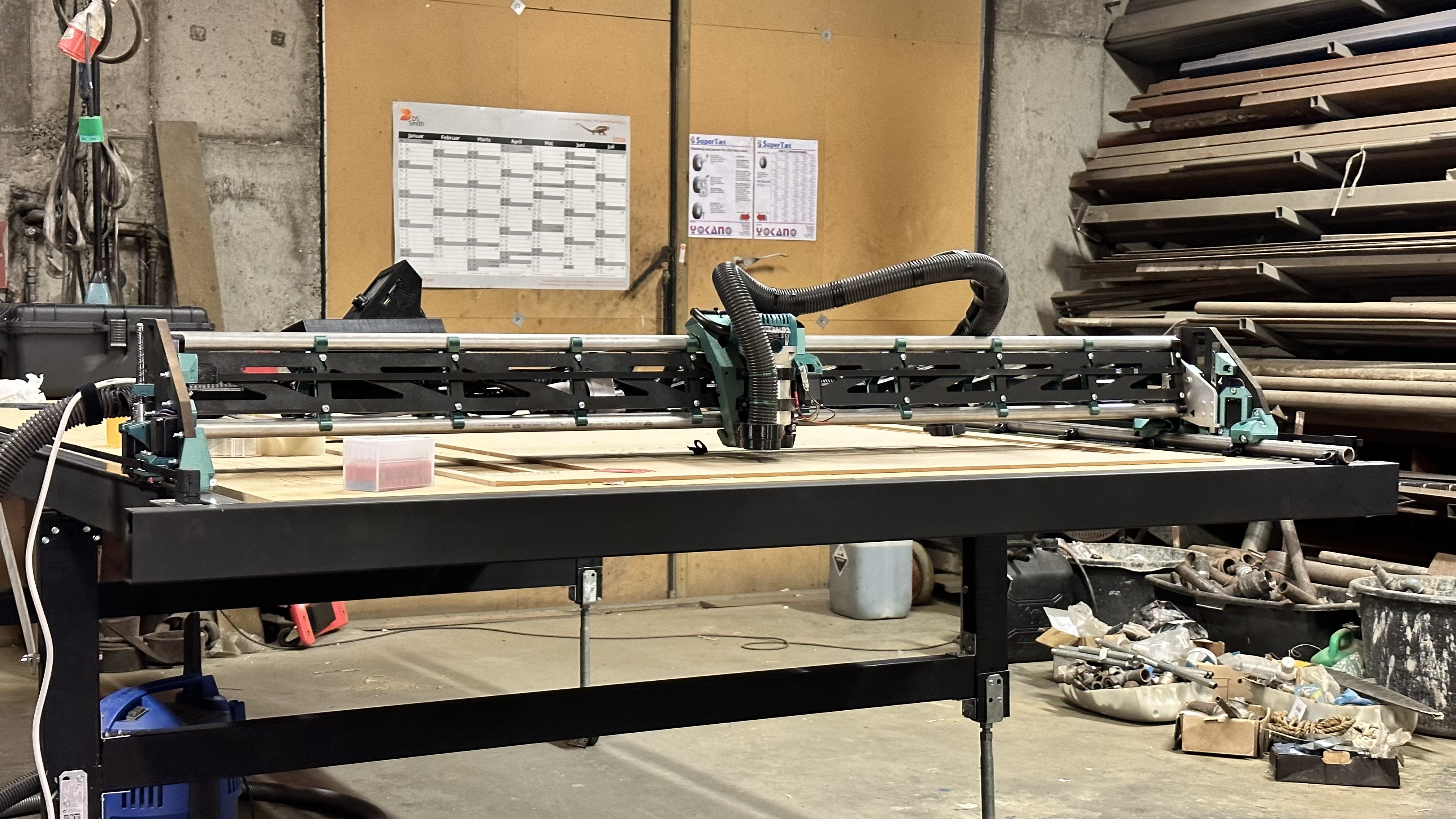
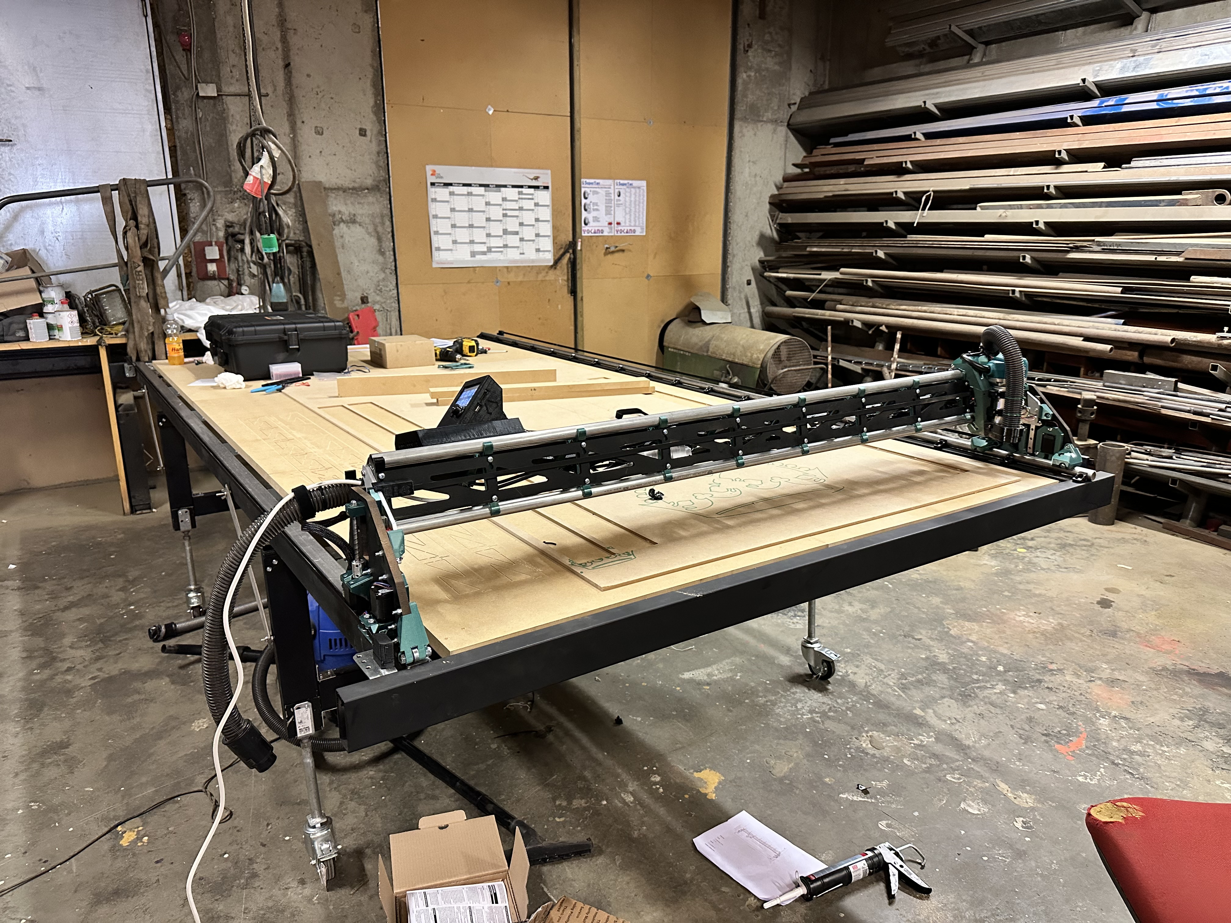
Hey, i finally got my LR3 finished, I’m very impressed with the design and can only imagine the time it must have taken, i could stare at it all day. :slightly_smiling_face:

Since i have a large size build area X1500 Y3100 i wanted to split the surfacing in three parts, but I’m not sure if my approach is wrong or not, something is off I think.

Here’s what i did and what went wrong:

I first homed the machine, manually moved the gantries with the menu to different spots (front, middle and rear of the spoilboard) and moved Z down till it barely touched the board, then noted Z position from the screen (Tft32 with skr pro v1.2). Overall it ranges from 132.2 down to 128.6.

To generate the gcode i used Jaimes surfacing generator with these settings:


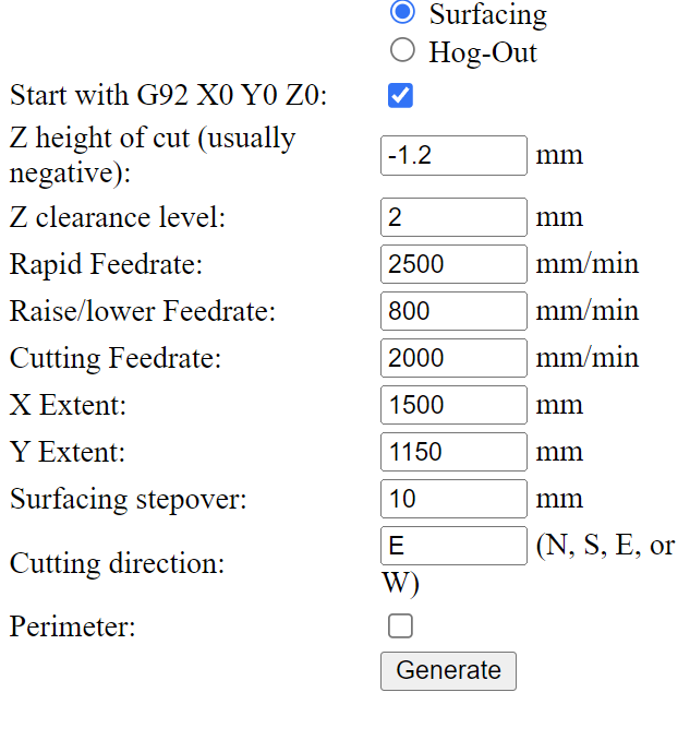
And then added G0 X0 Y980 Z132.2 before the g92 code (then it correctly moves to y980 and then starts surfacing movements past the middle part i want to start with) but it doesn’t remove any material even though it moves over the spot where Z132.2 was the high point on the tft screen. Also when i cut the strut plates it seemed the cutting depth was not always correct, about 0.5-1mm too deep.

My questions is then, is it consistent enough to split the surfacing up into three parts and do them individually, or should i take all of the 3.1m x 1.5m at once? In my mind it should be removing material on the high spot when, especially since i “measured” it with the Z position and started from that height, going 1.2mm own from there (next pass would be 1mm further DOC, ultimately getting to 128.5 (lowest spot)

Also i have squared the machine so it’s within 1mm diagonally, and leveled Z using the official guide Ryan made, Z is within 0.25mm. And the table is leveled with a laser even. The Skr pro has the dual endstop firmware from Ryan. All mechanical parts bought from the V1E store except the skr pro and tft (was sold iut)

The spoilboard consists of 6x 800x1128mm 25mm thick MDF
Also here’s the gcode
Midte Z132,2 til 131.gcode (704.9 KB)

In short i guess i am asking if i can count on the Z value is the exact same height every time i go to that position (except for the 0.25mm inaccuracy from my Z level)

And I know the adjustable legs look wobbly and unstable, works pretty good though, machine doesn’t wobble when cutting. Plus I can move it around the workshop :smiley:

2 Likes

I think your approach should work. It is unusual to use the Z coordinate after homing as an absolute Z position, but it should be stable. Typically people will touch off the workpiece and set zero that way, but your way should be more consistent for surfacing the spoilboard in multiple parts.

I don’t see anything wrong with your gcode either.

I suppose one thing you could do is home and measure the high spot multiple times, to confirm that the value is correct and your procedure is repeatable. Also make sure you lube the Z screws. When I first put my LR3 together and I hadn’t yet lubed the Z screws it appeared to be working and I didn’t realize it was missing steps and giving me uneven Z. (Although that would tend to produce the opposite problem, where it cuts too deep.)

1 Like

Alright actually I will check the tightness of the Z couplers now that you mention the Z screws. And also check for consistency :slightly_smiling_face::+1:

There were some inconsistency when I leveled Z, I had to home Z 3 times on each side of X where the two last times would have a closer value, and first more like 0.2-0.4mm difference from the last two, which were more like 0.025mm difference

And I totally agree the rods were pretty tight going when I assembled it so I lubed them as you mention :smiley:

Just reporting back, also for others in same situation as me - I checked for consistency as you said and that helped me find out that there was no problems with the software at least, and I could continue. It’s now completely surfaced! I tried fixing the tramming issue as well along the way.

I don’t know how important this is, but on my Y2 side (far Y); when installing the leadscrew, the motor axle and leadscrew didn’t touch, so the coupler would be semi-compressed, making that side a bit bouncy (I could press it down with a finger and it would compress more). Anyway it’s fixed now but I don’t think it’d make a whole world in difference. :slight_smile:

1 Like

I finally finished my lowrider V3 and want to surface my spoilboard.
I would love for some instruction on how to use the “Jaimes surfacing generator”, but am confused on what each of the parameters mean?
Eg. Im assuming “X Extent” and “Y Extent” is the size of spoilboard i want surfaced?
“Surfacing stepover” im assuming is the overlap of the tool?
“Cutting direction” is which way you want the cuts to happen, N would be +Y to -Y, S would be -Y to +Y,E would be cutting +X to -X?, W would be -X to +X? is that correct?
Z Level clearance is how high Z when moving without cuts?
Z Height of cut is how low below Home Z0 to cut material? so eg. -0.5 would cut 0.5mm below Z0?
The feedrates and Perimeter I understand (as i seen the listed Perimeter video for this). just bit confused with the other parameters.
For example, if i wanted to surface a X1500 by Y3100 spoilboard from mdf for a lowrider V3 how would i do this? Anyone know if a step by step guide is available?
Would i need to “TRAM” my lowrider v3 or is this not required on the V3?
Any Help would be greatful.

Yes.

All of your understandings seem correct to me.

If you want to verify any of it, generate the gcode and load it in NC Viewer and make sure it does what you want

1 Like

Thanks for the prompt response Mike.
So now lol how do a tram the lrv3? :slight_smile:

There are quite a few discussions here if you search “tramming” or “traming”.

Ryan has a tramming tool on his Printables you can use, depending on which Router you have, and there are some steps in the Docs here and here about getting it all set up.

I would follow everything in the Docs first, and then re-assess afterwards if you need any extra adjustments.

How trammed you need it will depend on what kind of cuts/engravings/etc you intend to make.

If minor adjustments are needed, they can probably be handled by shimming the router in the mounts with tape or something.

1 Like

I’m an inexperienced noob, so take this with a few pounds of salt…

I think that it would be helpful to make sure that your two Z endstops are aligned properly with each other before you start trying to adjust the router perpendicular, or to start cutting away at your spoilboard…

For example, if you measure the bit height at XMin and at XMax, and you are consistently out by the same amount all along the Y axis, then you probably will save yourself a lot of time and effort if you first adjust the endstops so that the gantry is the same distance from the surface at each end. Otherwise you are tilting the router and cutting the spoilboard to compensate for a skewed build.

1 Like

That’s the Z-leveling link I put in the post above, however, that Z level doesn’t really matter for getting the tool perpendicular to the gantry and being able to surface.

However…

It is definitely important to Z level first, as that will make it so that you have the least amount of material to remove when surfacing, and if your surface board is roughly flat, makes it possible to use the tramming tools effectively with the spoilboard as a reference. Z leveling first will make the rest of the process much easier.

That’s more than most people need to understand though. If the parts are printed well, it should be pretty close to perpendicular, and just the Z-level is good enough for most

2 Likes

And from what I have read, surfacing is not required for most either, unless you plan to do some very detailed carving.