I built a Primo with a 24" X 24" cutting area and now just need to cut the spoilboard, which will sit on top of the table and will be screwed down, but am not sure what dimensions to cut it to.
The actual cutting area after drawing the largest square possible with the Dewalt 660 mounted without crashing into the sides or endstops is actually around 23.25" X 23.75".
So, would it be better cutting the spoil board rounded a little over the cutting area by making it 24"x24" or a bit under by making it 23"x23" or approximately 23.25"x23.75"?
My concern with making the spoilboard 24"x24" or larger is that I will end up making a pit after surfacing the spoilboard and later have difficulty cutting over sized boards.
In this case, I plan on using and surfacing a 3/4" MDF, which was what was left over from my MPCNC table made from a full 3/4" 4’x8’ MDF sheet cut in half and will drill a grid of holes to add threaded insert nuts, but am unsure if it really matters if I go an inch over or under the cutting size.
What you do not want to do is to go over the cutting size (including the diameter of your biggest endmill) because if you plane it, you will have ridges and can’t place workpieces on it any more that overlap the edge (because there is a ridge then).
Yes! So many of the builds photos I saw before I constructed my first V1 machine had the spoil board extend beyond the cutting area. Even the V1/Primo calculator assumes the feet are at the same level as the top of the spoil board. The smarter builds had cuts in the spoil board to easily replace the spoil board without required the CNC to be remounted, but still there is a pit. This is how I built my first machine (Burly), and I ended up with a pit.
When I upgraded to the Primo, I made my spoil board the same size as the cutting area and used the router with a chamfer bit to position it. Note that the surfacing bit is typically 3/4" or 1", so there is no issue surfacing if your position is not perfect.
Another thing I did was run the wires the long way around so that the cable chain was at the back of my machine. This makes it much easier to put stock in from the front. Another solution I’ve seen for this problem is to construct a “tray” between the legs so that the cable chain rides above the level of the spoil board, and stock can be inserted below the tray.
So, if I used this 1-1/2" surfacing bit Amazon.com and the radius is 3/4" that should compensate for the less than an inch difference in the cutting area if I cut the spoil board exactly to 24"x24", correct?
I’m not any kind of expert, but, given we are using trim routers, I wouldn’t go above 1" in diameter for the surfacing bit. And yes, the radius of the bit will extend beyound the working distance.
Cable sleeves are fine. I mostly see cable chains in the photos. My comment was more about where you place the chain/sleeve. If you place your electronics at the front of your machine (like most of the builds), then running the sleeve at the back of the machine will be a longer wire run. But having it along the back gets it out of the way for oversized stock inserted from the front.
Is it better screwing down my spoilboard first, then surfacing and then drilling the grid of holes to add the threaded nuts from the bottom or drilling the grid, inserting the nuts and then surfacing after?
Also, is a 3"x3" grid spacing more useful than a 2-inch or 4-inch grid?
I ask because I was in a very similar spot as you with MDF spoilboards on my MPCNC and I was asking for advice on surfacing. The response that I got was not likely to be needed and more of an advanced task.
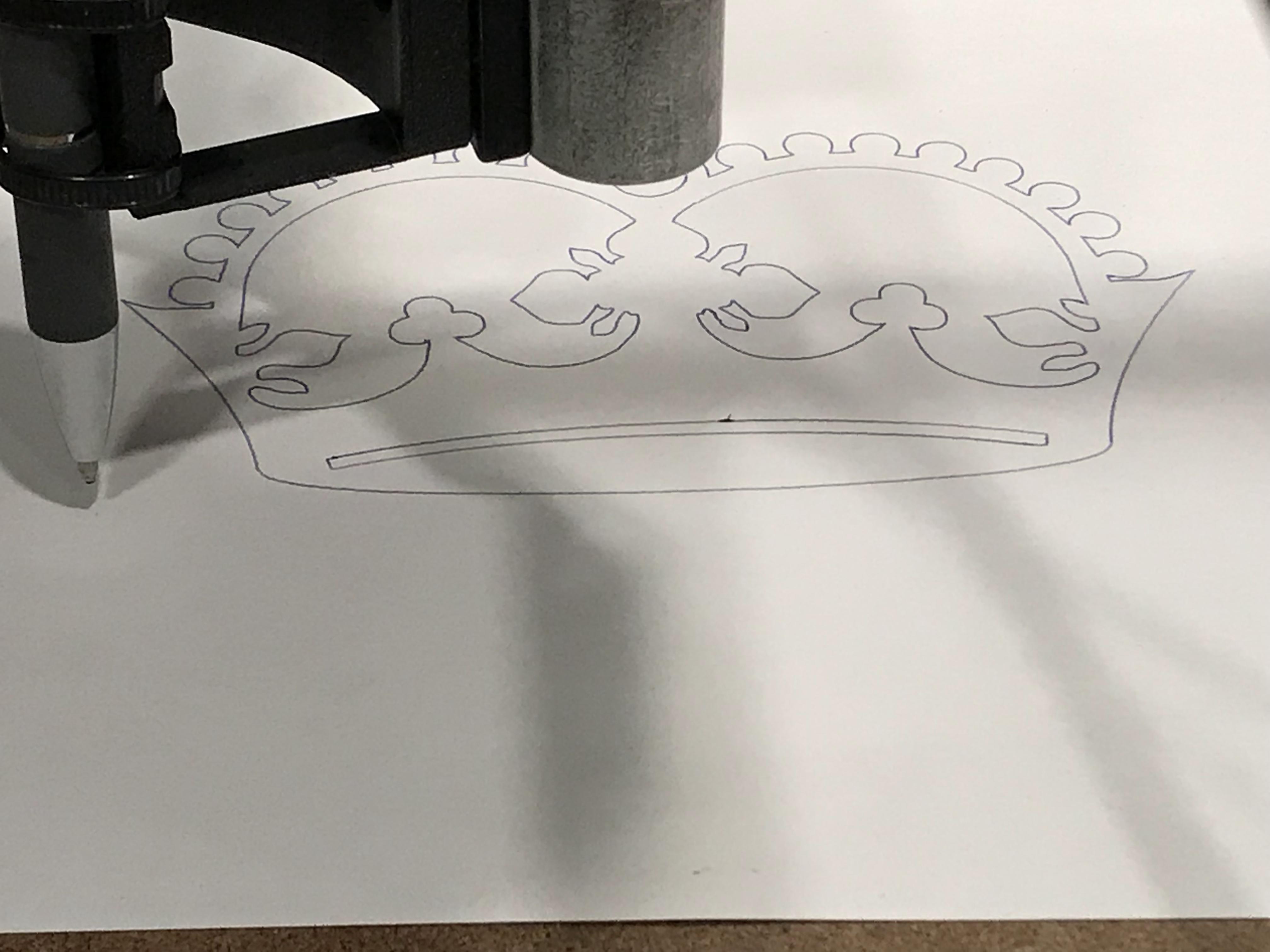
I did the test crown and it turned out better than before I had the spoil board w/ marker.
Once you get the test crown carved, then you can see if you are having leveling issues.
Not a grid but I am using t track at a 3" spacing and have been pretty happy with that so far.
I haven’t done any test carves yet, just the test crown with a pen, which came out okay. The circle in the center is a little skewed for some reason, but it could be the way it was mounted.
I need to mount my spoilboard to the MDF table base first, I think I’ll do one hole near each corner and maybe 2 near the center that are all countersunk with washers.
Do you think the 6 screws will be enough to hold it down evenly or should I add two more on the center sides and how deep should the screws be countersunk considering that my spoilboard is 3/4" thick?
Your t track setup looks really good. I was thinking of doing something like this, but thought I should keep it relatively simple as this is my first build as well. https://www.youtube.com/watch?v=wm2yL85eNJE
Looks fantastic. The center jewel is deceiving since is it is not a true circle in the file.
My MDF is also 3/4" and I countersunk them down to 1/4" and they are holding well. (i.e. I drilled 1/2" down into the board. ) That will give you some breathing room in case you carve a bit into the board before you hit the screw.
For screw location, I would agree with your plan. That should be enough to hold it in place.