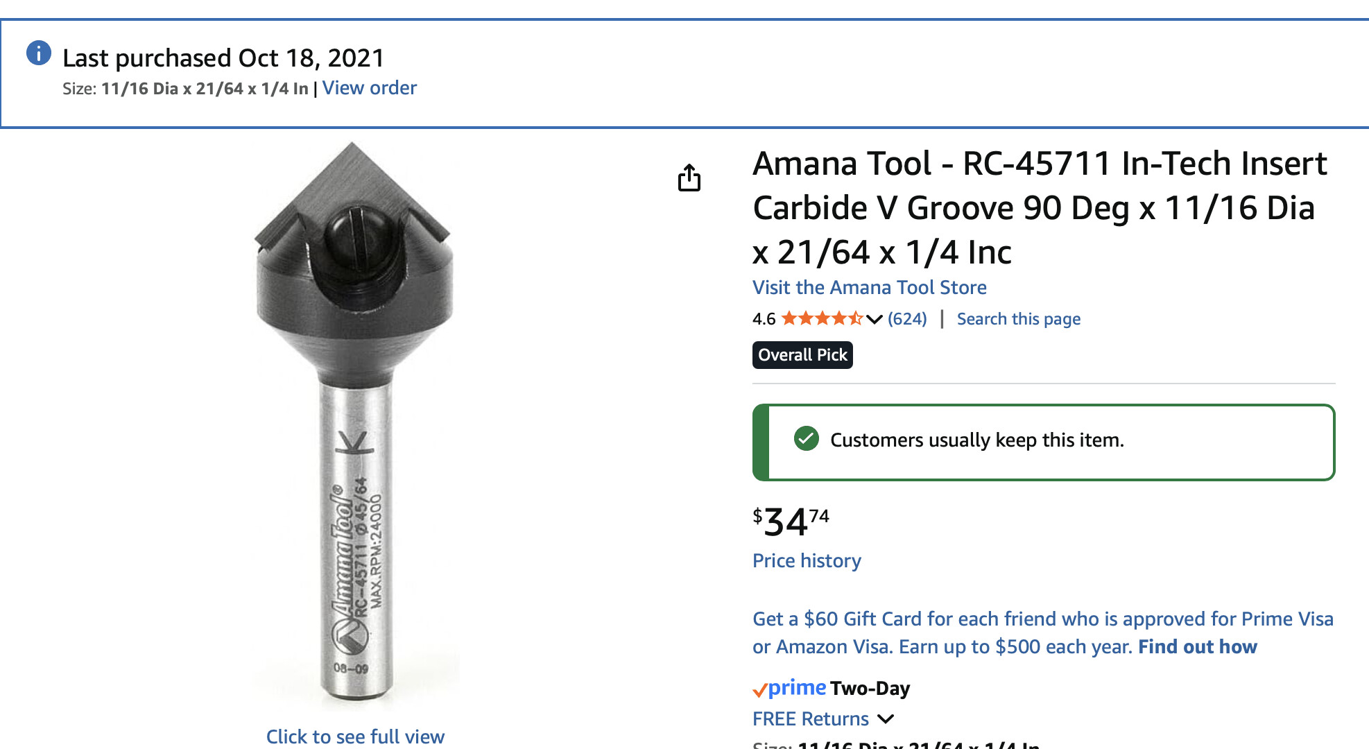
I am just too lazy to mill a skim coat off of my MDF spoil board. I wanted have a graphical check and decided to use an Amana 45º (90º) V bit I just love.
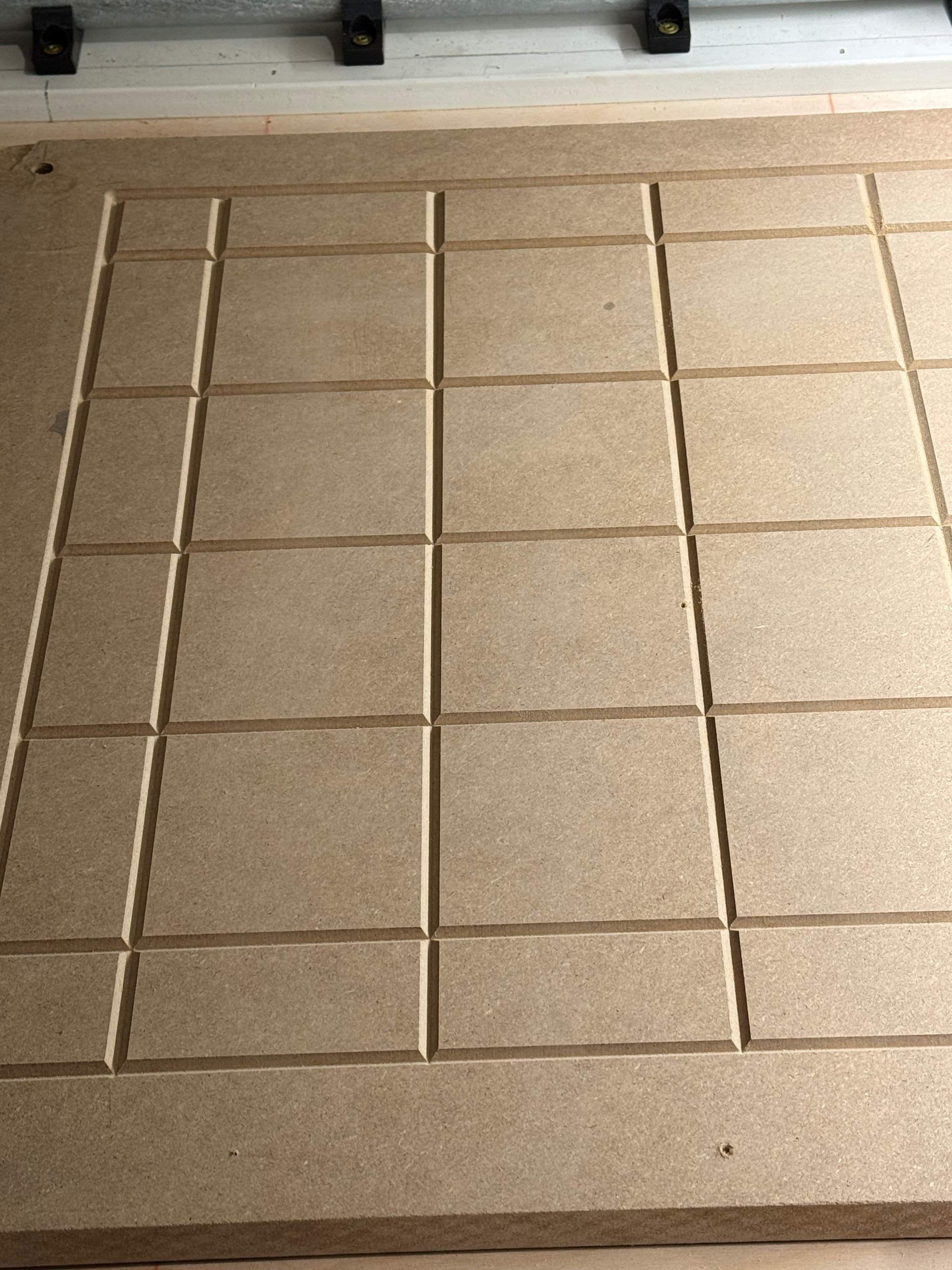
I used to cut 100mm grid at 2mm deep knowing that doing the math the width at the top is double the depth so 4mm wide, for 2 deep.
This gave a very quick “topographical” glance of the entire area.
It’s hard to photograph because of parallax but in person is easy to see and measure where it’s wider or narrower. I also like the groove for reference and if possible driving the hold down screws in the valley. As well as sawdust (or should I saw cutter dust )
It all comes down to what you use it for and how far off your table actually is.
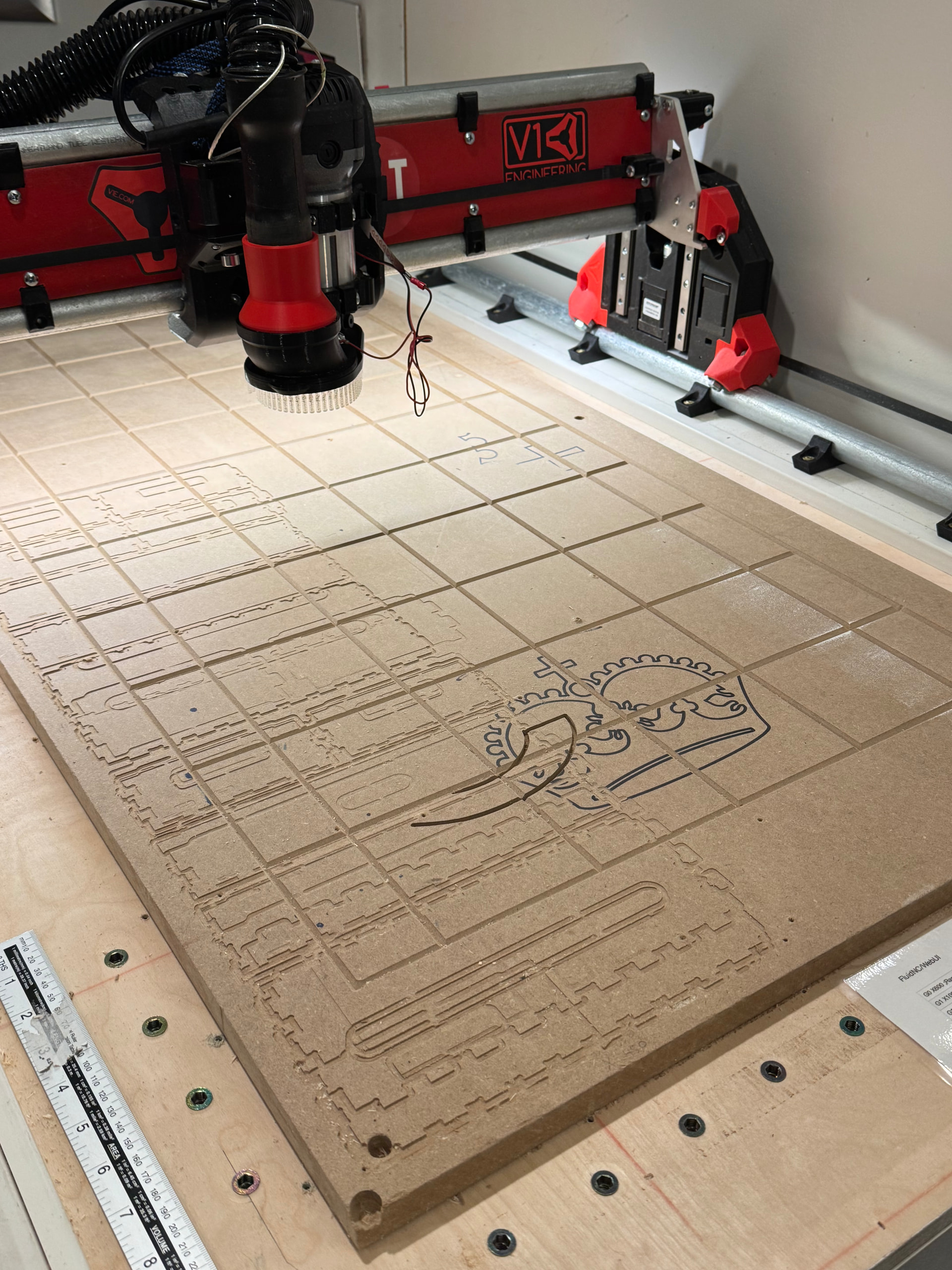
I just surface my big machine I took 0.4mm off the surface in two passes. 0.2 took off a few really high spots, 0.2 more got most of the rest. I am left with a semicircle at the very front that is probably 0.1-0.2 low. I can live with that until I surface it again.
If you don’t deal with Z depth accuracy much it is no big deal at all. Through cuts don’t really care. Or if you do surface carves, and you surface your material first, same deal, no need for a perfect table.
I guess you probably know my stance on all this by now. I think a lot of people chase zeros because it is kinda fun, and we all want “perfect”, but when has it ever mattered if your drawer box, arcade, or house sign needed to be more perfect than 3-5mm?
epoxy inlays care, but that is the only time I’ve needed to worry about it. and only beacause the board will look funny if it isn’t leveled, but you can check that and shim it before you cut if you have to… or so I’ve heard.
As long as you are only cutting wood it’s also more forgiving. I never bothered to dial in my new CNC perfectly, opposite to some other people who only do aluminium. There it matters a lot more.
Think of it this way. Your Z endstops are fixed, randomly above your table. The first Z calibration sets your beam ends to level over the ends of your table in relation to the endstops. At that point your beam will always hit the same position after homing. The second calibration is surfacing the table to match your now fixed beam level.
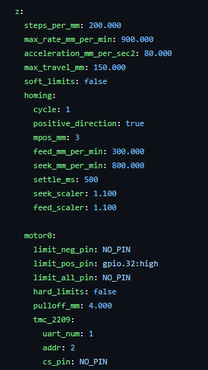
pulloff has to be larger than the endstop rest distance (ours are about 2.5-3.5mm at our homing speed) and yes this set the level.
After each side has pulled off to its own independent distance, then is sets the Z current position to be mpos_mm, in this case 3. (usually this is 0, but why throw away the 3 free extra millimeters).
Thanks actually had good success from the get go following your doc’s.
I was just verifying that to me this is the only adjustment of the beam as the Y-axis is fixed on the table. Which it is.
I did just think of a question I wondered about.
The Z_STOP_MIN/MAX that that houses the microswitch is held on with a slotted screw opening and also somewhat allows some minor rotation. I have accidentally bumped it a few times. No issues just always check it all good after my flub.
Just was curious what is the freedom to physically position typically used for versus the programable pullback settings?