I have just put together a new controller box for Estlcam 12 to work on my old CNC router that was running on Estlcam 11.
The controller box is almost identical, changes being now a metal box and the grounding has been isolated from the negative supply.
Everything (almost) is working fine except for two things, the probe and the spindle.
The probe I have disconnected physically for the time being and un-set it in the setup.
The spindle will turn on and I can adjust the speed no problem, but when it is turned off it doesn’t turn off completely, just slows down and makes a ticking noise. I have to disconnect the power to stop it, turning the power on again and it has stopped and waiting to be turned on again.
The VFD is a YL-620-A and the spindle is a 1.5Kw air cooled.
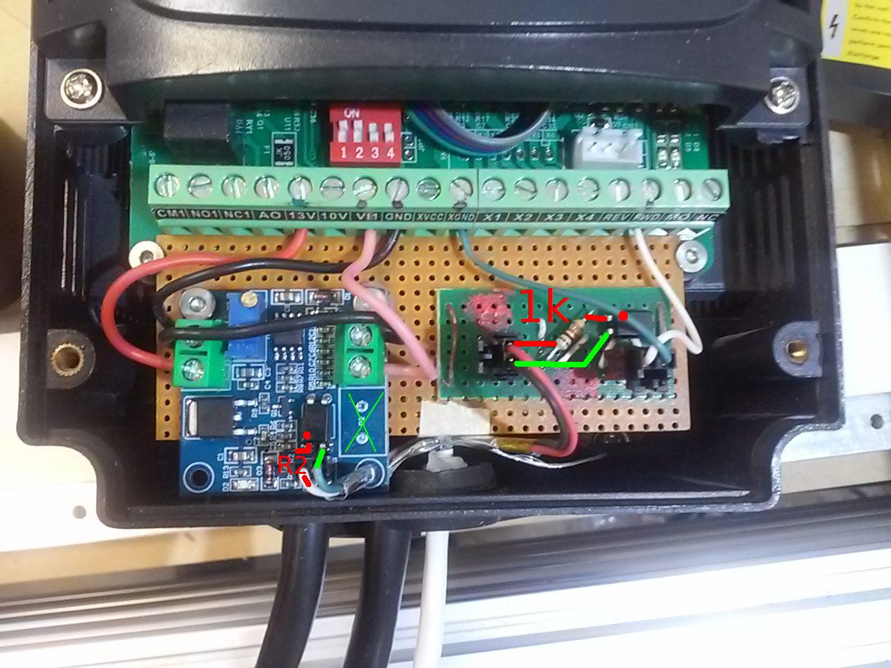
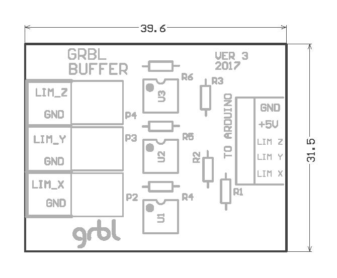
The wiring is as shown below as supplied in Estlcam 11 setup screen.
The output has been carefully set to 10 volt for 24000 rpm.
One other thing that was different from the setup was that I had to invert the spindle output for version 12 as when powered up the spindle was running flat out. I can’t understand that as the wiring is identical to the control box for version 11.
I have checked and rechecked the wiring and I can’t seen anything that is different, although I may have missed something that I can’t think of.
The probe I will work out later after getting the spindle sorted first. Maybe I need to put a capacitor across the connections or something. The wiring for that is just pin to ground, and I have a couple of spare PC817 isolation modules not used, so maybe I can work out how to use one of those for the probe.
Edit:
I just did a physical test with the machine and all went well until the very end.
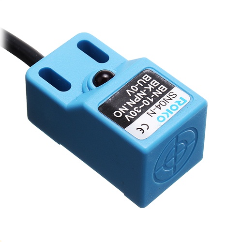
The spindle stopped as it should but then started again slowly, but not really slowly because it was starting and stopping contiguously and also the limit switched (SN04-N) induction switches were flashing on and off with the spindle, so obviously there is something wrong there that I need to look at. Otherwise all went well .
Maybe the pwm regulator for the spindle is broken or not configured correctly? Did you adjust the screw with 100% power to be 10V? At least I had to do that with my spindle..
The spindle is working properly and so are the limits. Probe is still giving an error, not looked at that yet.
But at the end there is the problem, seems like there is some interconnection between the two circuits, but after checking all the wiring (many times) I can’t find any fault.
I have to switch off power to the spindle to stop the problem, after it stops the problem has gone away when switching on again.
In Estlcam there is a command where you can give full power to the spindle, pwm100. If you set the speed to 100%, then use pwm100 and adjust the speed to 0%, does it stop?
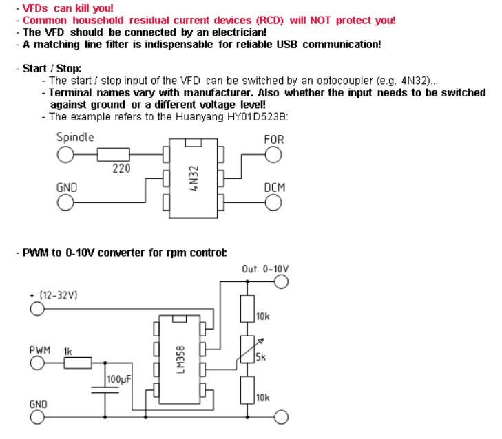
disconnect the VFDs run signal cables from the 4N32.
If left open the spindle should stand still.
If the two wires touch the spindle should run.
If left open again it must stop completely.
If not: check the VFDs manual.
If not I’ll have to check why the output is inverted.
The spindle not powering down completely may be due to a “weak” 4N32 with low amplification or the VFD needing too much switching current.
Try a different optocoupler or lower the resistor to something a little smaller like 150 Ohm (but not much less).
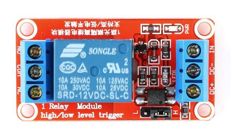
Or use a relay to switch the VFD run signal - but keep in mind that you cannot just connect a relay directly to a arduino mega - you need a relay driver.
This problem will shift to the “on” side if the VFD was set to the wrong on / off logic.
Thanks for that info Christian.
Some things to try tomorrow.
What I don’t understand is why the limit switches are being affected. They are all connected together and the limits are working fine, until the spindle turns off. Then the spindle very quickly stops and starts and as that happens all the limits are flashing.
I have a few more circuit boards with 4N32 and if needed I can make another board using PC817 instead.
The same FVD was being used with version 11, no changes have been made to the VFD settings.
When running for the first time using 12 the spindle was running and I had to invert the settings in CNC program to stop it running and when testing with a cut it worked OK, except for the ending when the rapid stop/start issue became apparent.
I made a new board up this morning using a 150 resistor. I connected up and tried it, but the same problem.
An error message comes on the screen at shutdown of the spindle, it says limit triggered.
I took the limits and also the probe out of the settings and also disconnected the limits physically.
The problem still persists. Everything works fine until the spindle tries to stop. There is a ticking noise that sounds like a relay switching on and off at that time and it also is timed at the same rate as the flashing of the limits (when they were connected) but the same ticking is happening now the limits are disconnected.
The sound seems to be coming from the spindle, but it is hard for me to be sure as I have a cochlear ear implant and all sounds seem to come from one direction for me.
I tried to disconnect the signal wires as you suggested and the spindle doesn’t work at all then, and if I connect up again it works but on shutdown there is still this problem.
I have a relay that I could try, not sure how it should be used in this case.
I would imagine that the relay would need to have it’s own power and the signal in would be connected to 04 spindle on/off on the Arduino Nano.
The relay NO connections across the DCM and FOR
I think there is something else going on here, seems like a cross connection or something.
I have checked the wiring and I can’t pick anything out of place.
I am not sure if I can just connect a couple of wires together through a relay without blowing something up. The 0-10 volt side is working good, the photo coupling seems to be working OK too, but why the problem at the end and what connection could there be to the limits?
How does the machine run w/o limit switches? I’ve never got around to hooking any up. I didn’t know you could use a single input pin for multiple 3 wire NPN sensors, I was planning to use 3 on a 4x 24v > 5v optocoupler board.
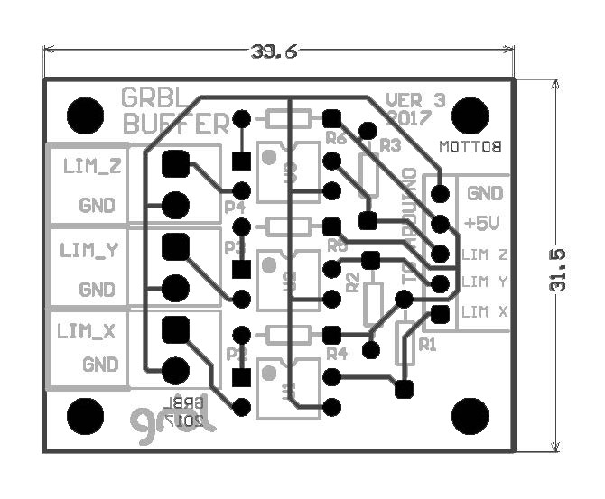
I have a GRBL opto isolator that I found some years ago on YouTube. The Gerber files were available for download, so I got them and then had China make me 10 boards.
They are designed for X Y and Z, but although they are all on the same small board, they are separated from each other, so you can use then for whatever you want to isolate.
I have all the limits wired in parallel and am using NPN induction limits. Estlcam does a very good job of controlling the machine while homing, first Z, backs off and reads again slowly, then X, does a quick movement close to where the limit is expected, slows down, does the first pass, then backs off and reads again slowly, followed by the Y axis same method.
All this on just one pin and a 5v supply for the limits themselves.
I got use to not using limits for the last few years, but as I am building a new control box I thought I would add all I can to it. Hence the problems now ha…ha…
I am using a 24V supply and a stepdown for the lower voltage stuff, I can adjust it to what I need, but the sensors will work on 5 volts no problem, but safer to set the voltage around 6 or 7 volts unless you have nothing else that requires a maximum of 5 volts.
Looks like the same VFD I have, except yours has a four position piano switch, mine only has the position for it. Neat way you fitted the little boards inside the case, I wish I had thought of that.
Christian said that I could connect two wires together to test switching the spindle on and disconnect for switching off. I would imagine that he meant the FOR and XGND terminals, but I am reluctant to do that because I don’t know for sure. I don’t want to blow it up.
This morning I changed over to my old controller box and ran version 12 without the spindle problem, so it proves that the problem is in my wiring of the new control box.
So next step is to take all the wiring out and start again because after taking bits and pieces off for testing it has now become a birds nest.
I still don’t know what is going on, but I am sure to find it as I rebuild.
Sorry for wasting ever bodies time on this issue
You could be right Mike.
Worked all say on rewiring, I will give it a test tomorrow and see if I have sorted it. If not the photocoupler may come out.
There is a good chance that is the problem as the limits are affected, even when not connected, but the photo coupler is still in the circuit.