Sonofa....dangit(+ my primo build!)

Well, I THOUGHT I had all the parts I need for the primo. Turns out that bag of idler pulleys I found stashed away are not 10mm, they’re 1/2 inch. So they don’t fit in the trucks.

Do I go print some and try to get the bearings out of these without mangling them, or just hang it up for the day and wait for the right pieces?

Yeah. Order the right pieces.

1 Like

Ouch. It’s worth the wait

1 Like

Back in business, thanks @vicious1. Hopefully I can get some free time before the weekend.

2 Likes

Got some free time, stuffed the belts in the trucks, and now I can’t find one of my 16 tooth pulleys.
ARRRRGGGGHHHHH!!!

1 Like

Slow down and take a deep breath :triumph:

I don’t know why, but I often think of asking in the forums when I misplace something. “Does anyone know where my flush trim cutters are?”

5 Likes

Probably right where you expect them to be, given that you misplaced your wire stripper…

I needed a deep breath for that yell!

1 Like

So, got any ideas?

Don’t tell me I have to go find THAT now, too!
It’s almost certainly under something. I definitely have to wait for the weekend so I can clear some things out of the garage.

Did you check on all the motor shafts? Did you count them again? What about the pockets of your dirty clothes? Do you have little kids that like to eat pulleys?

If you didn’t make a simple or common mistake, I cant help you.

1 Like

Yes, they’re kids, not Oompah-Loompahs. Even after they’ve been rolling around in Cheetos after lunch…

Doing anything in my garage is like those puzzles where you unscramble the numbers by sliding the tiles around… And I’m planning on adding yet another rolling bench. :slight_smile:

2 Likes

What about something like this? I think I’d put my small mpcnc on the bottom.

2 Likes

Well, never found it. Starting to question whether I ever had it.
Big HUGE thanks to @tgm022861 for hooking me up!
Here’s how I set up the corners for squaring. I cnc’d the boards to mount the feet in, so I could fix one side to the bed, then one corner from the other. That left just one corner to pivot and measure. Easy peasy. Not as nice as having all 4 like I did on the teeny tiny, but still easy.


And after putting the locks on…

By the way, I really like the grbl, but I’m gonna need to go with the mega 5x and get dual endstops working here. I think I can square off the machine.
X1 Max

X2 max

But Y max hits the truck, and leaves a gap

I’ll measure it and print something for the other side. Looking at the way the belt holders are set up, I think I can turn those out and make small adjustments on the x, maybe the y too but that might be easier to just shim my block.

Anyway, here it is moving with my burly z, as motivation to get that speed controller working on the 660. I have all the pieces printed for the primo Z.

Also, 4 ft is DEFINITELY too large. This is the same tube I used on my teeny tiny. I swear it didn’t flex that much in the store :thinking:.
I might try a super thick stainless tube, but that’ll be about 40 bucks for just the one piece. I think the right answer is going to be shrinking X to 3 ft but I’m going to see what kind of chatter I get first.

Tomorrow I work on the spoilboard and calibration.

Just now I was noticing the same thing and deciding if I was going to print little spacers to sit on the side rails so that the Y max would hit the limit on the corners (with spacers) instead of the gantry hitting the truck. Should be trivial to whip out a simple part for that.

1 Like

I just measured my gap. It’s at 0.490". I’ll call that a half inch. The stop blocks are just over 0.6". Gives me a tenth of an inch extra. Being the lazy soul that I am, I think I’ll just use the extra stop blocks I have (since my dual stops aren’t set up right now) and if I like them, print a couple more. I’d rather have half that, but not so much that it’s worth putting in any effort at all, lol.

1 Like

Brilliant! I’m printing stop blocks now (I had skipped them before).

1 Like

Well, i got the machine all squared up by bumping it into the back corner. I’m surprised that it actually worked at all. I kinda figured the belt mount would bump into the corner and not be repeatable, but it seems OK. loosen one side, then tighten the other. the stop moves either in or out, bingo bango.
Then my wife tells me to just order a board that can use the dual endstops, lol.

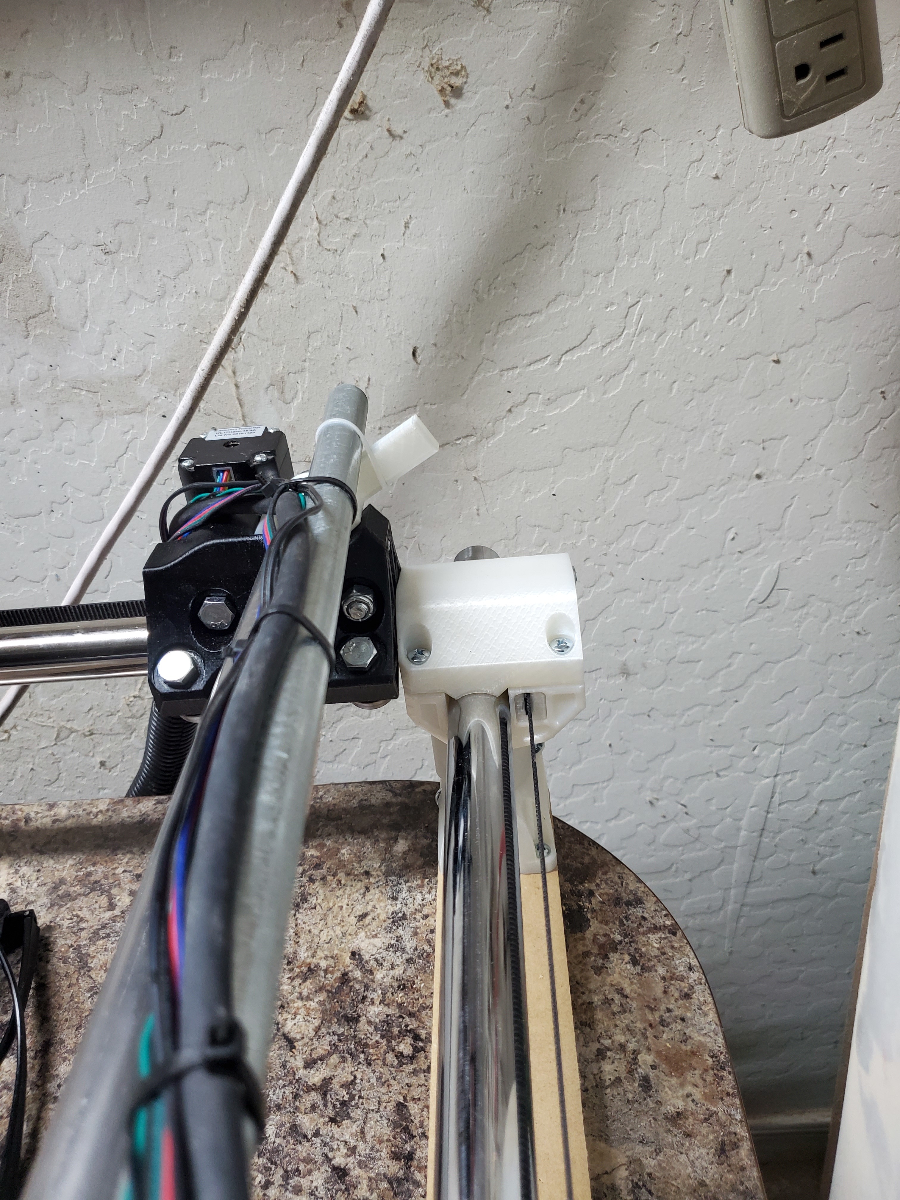
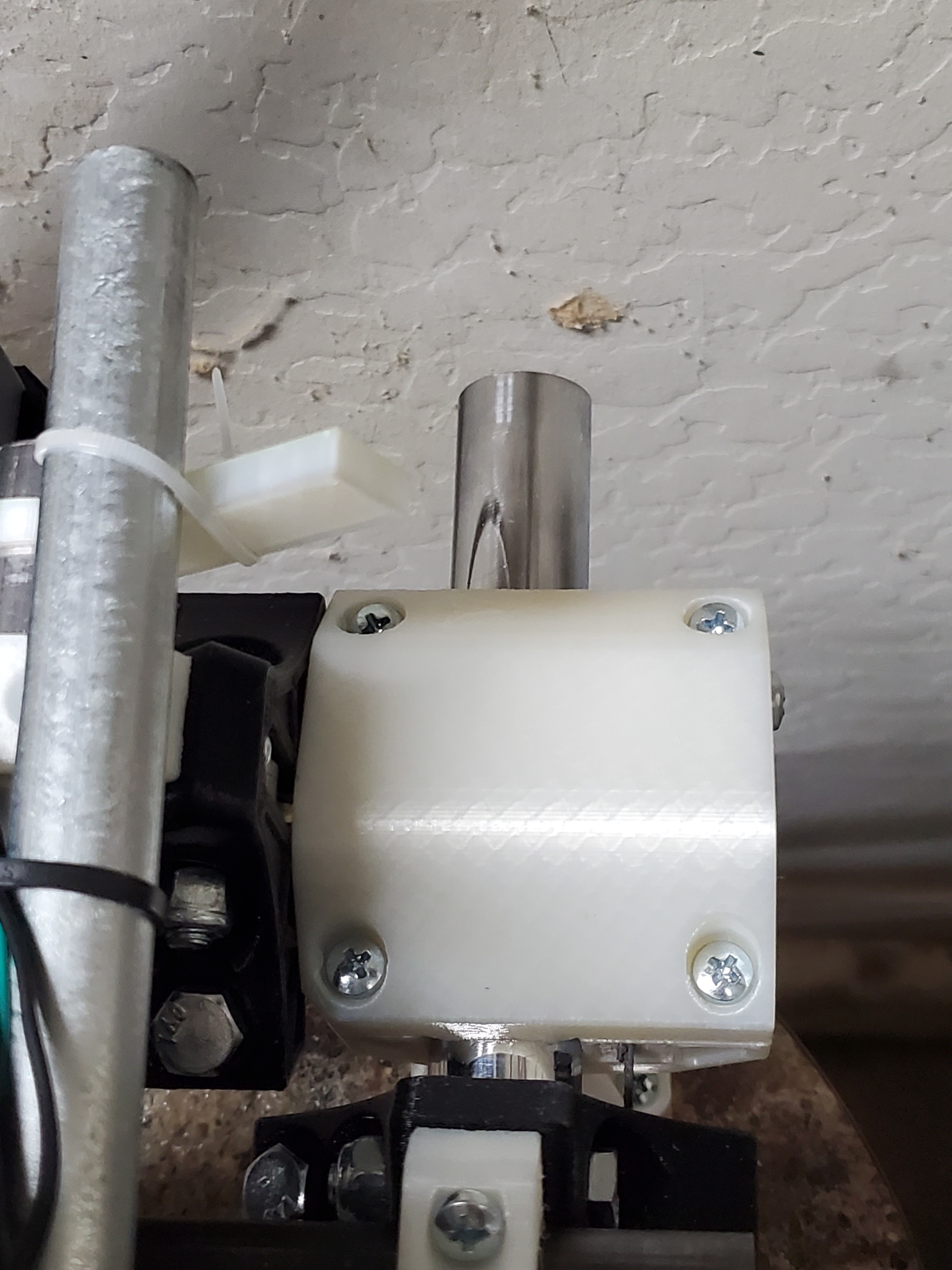
Guess I never updated that, lol. Got the dual endstops on!
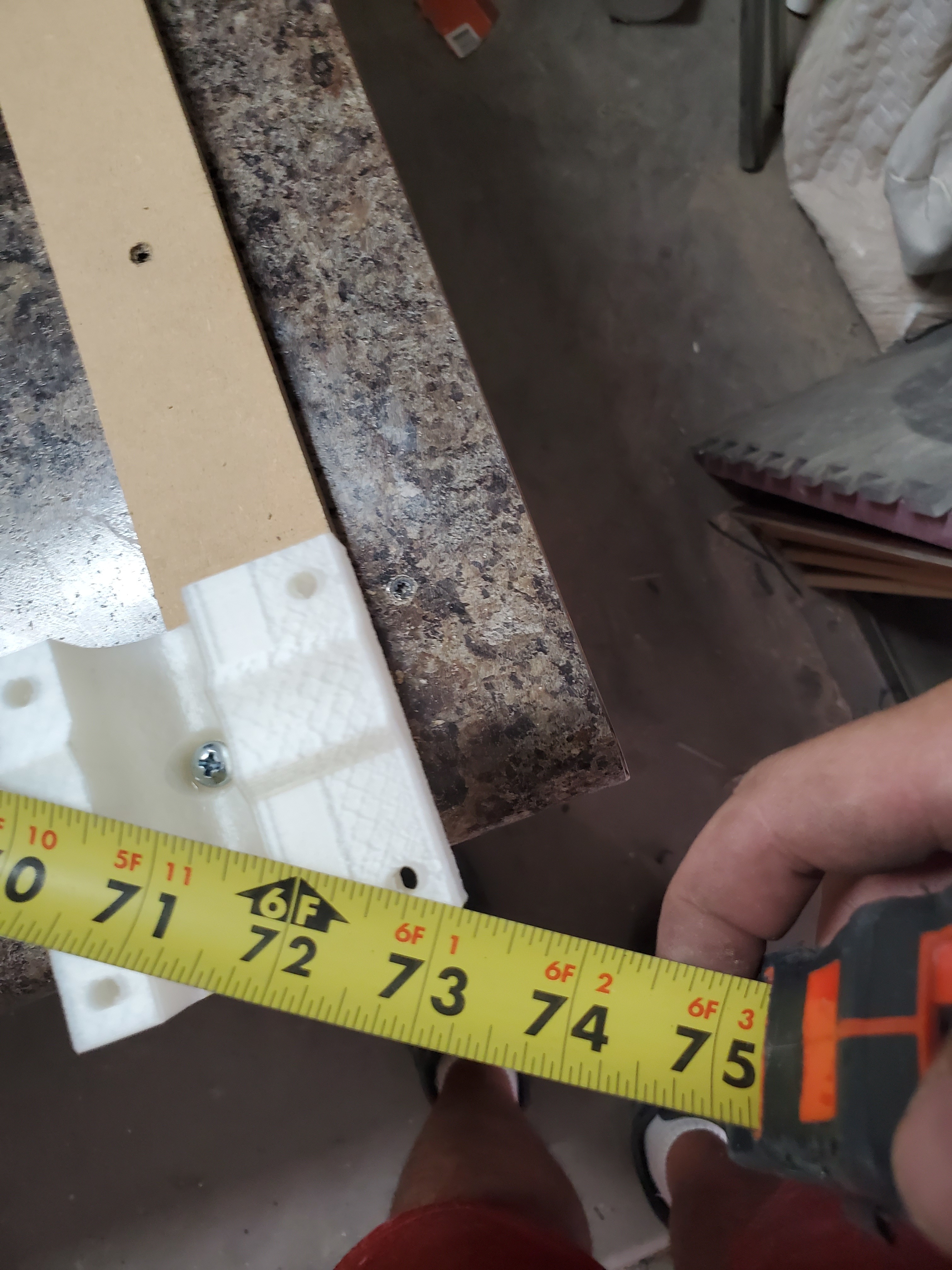
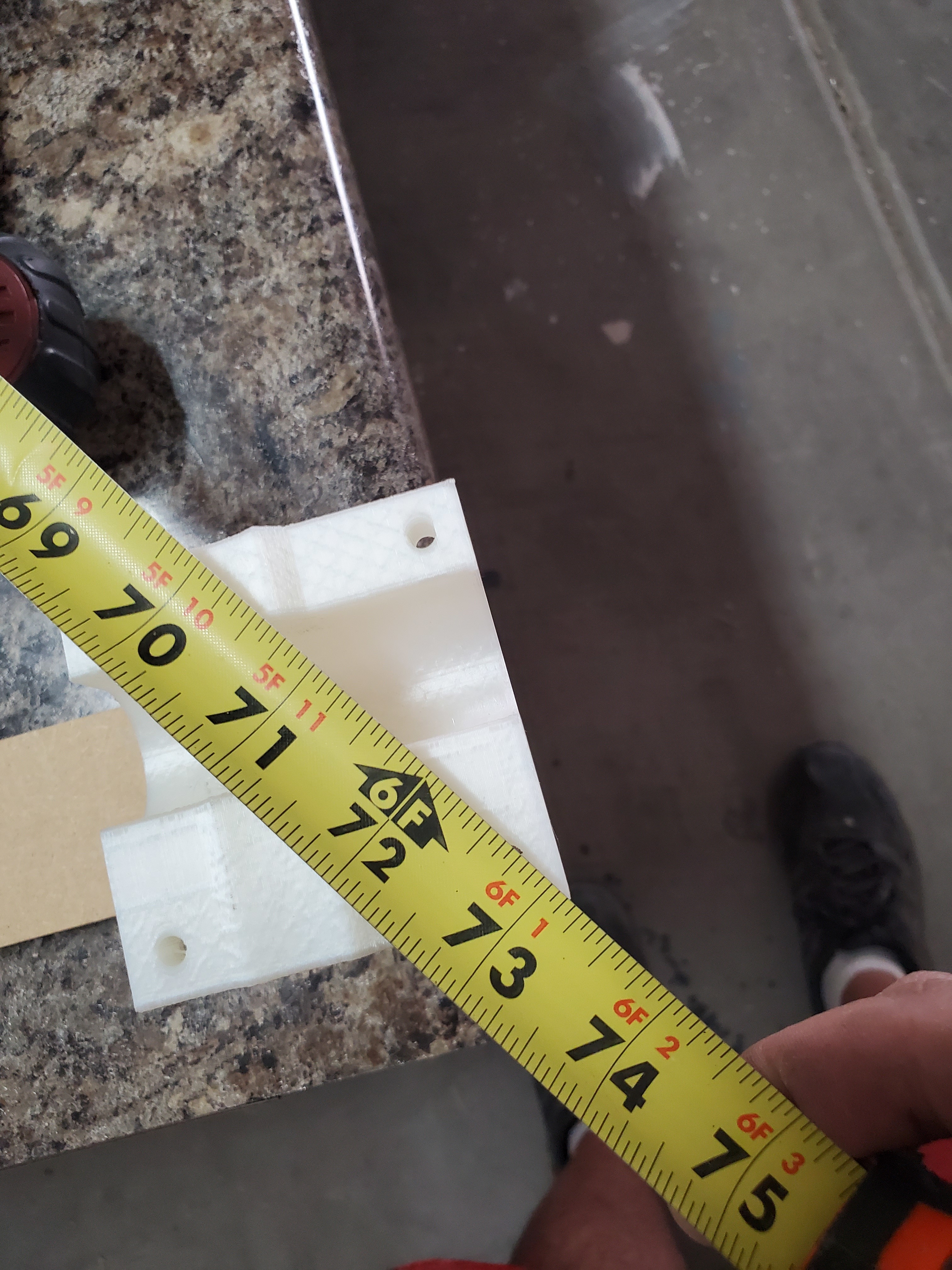
Also got tired of cutting into the spoilboard in one corner and not even through the stock towards the middle. Left me with a lot of trimming and sanding to do, and wifey has started selling some of the stuff I make, so ain’t nobody got time for that! Some places it was a good 1/16in or so.

I went back and forth on surfacing the spoilboard. I read every thread I could find here. I think I have a handle on the issues it MAY introduce. And it seemed kinda like a lot of cutting to solve this one problem. Indeed, I spent about a half hour creating the toolpaths (took 3 go’s to get it just right) and probably 6 hours cutting (multiple depths/attempts, several starts on each of the 2nd and 3 attempts). In the end, i took off a lot more than I wanted to. BUT…

I got the dreaded ridges with my 3/4in router bit. Primo core, and I’m mostly sure my printer prints square in the z. I did run the V1 test after I printed my core (which is when it was released). My legs are all short enough that the corner pieces were all collapsed and touching.

But I figured the old desk I’m using is slightly wonky. I know it is for sure. Weighs about 200 pounds and I rolled it home down the street on end using a hand truck. Then I moved it next door (where I’m now renting) on a couple dollies. And the primo feet are mounted on top of mdf. And I glued/screwed a demoed laminate countertop onto it to get more area. So, lots of things to go wrong.

I tweaked the legs a bunch during the second run bendy it was the only way I could think of to tilt the core, and a few times before the last run.

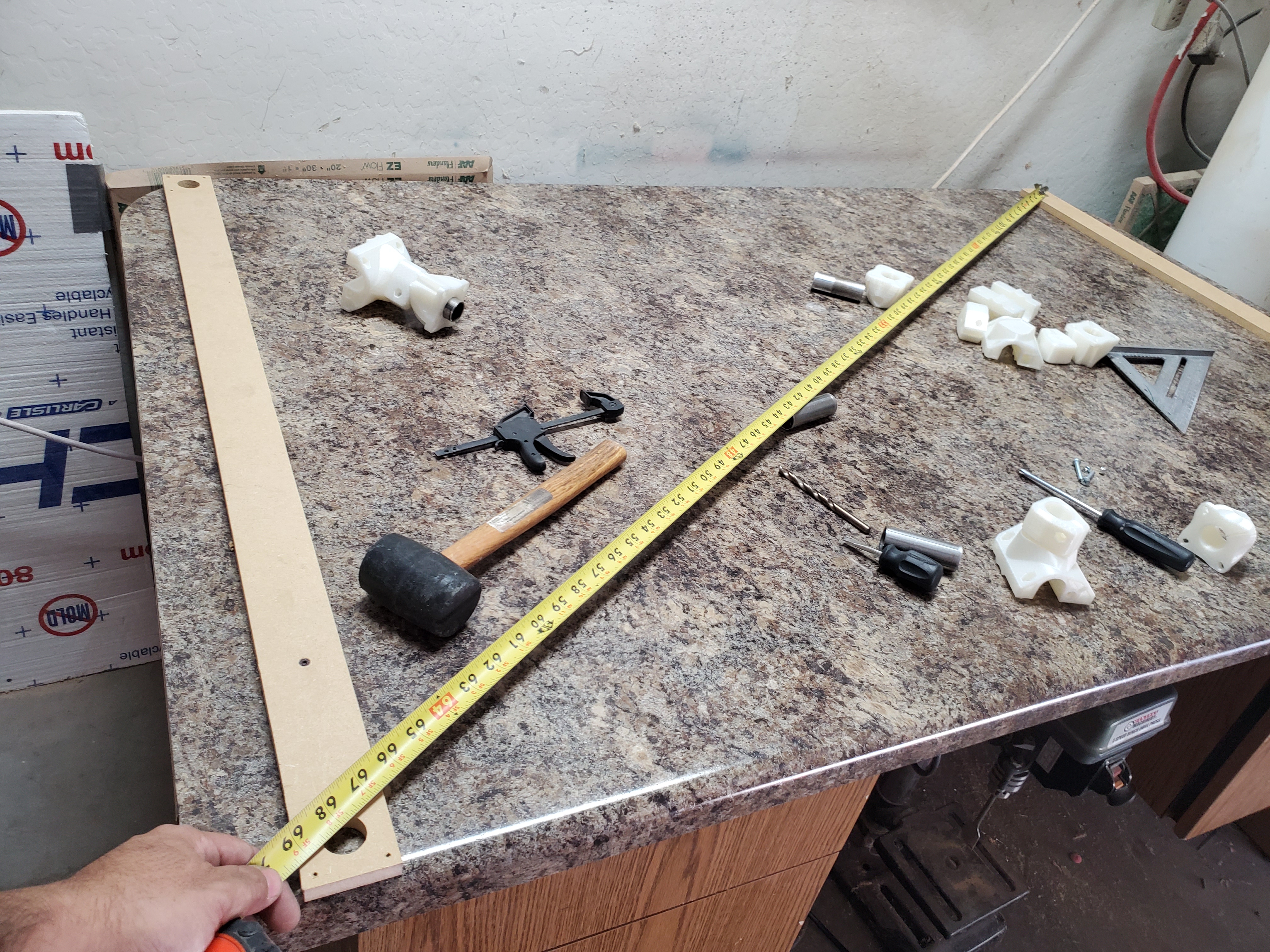
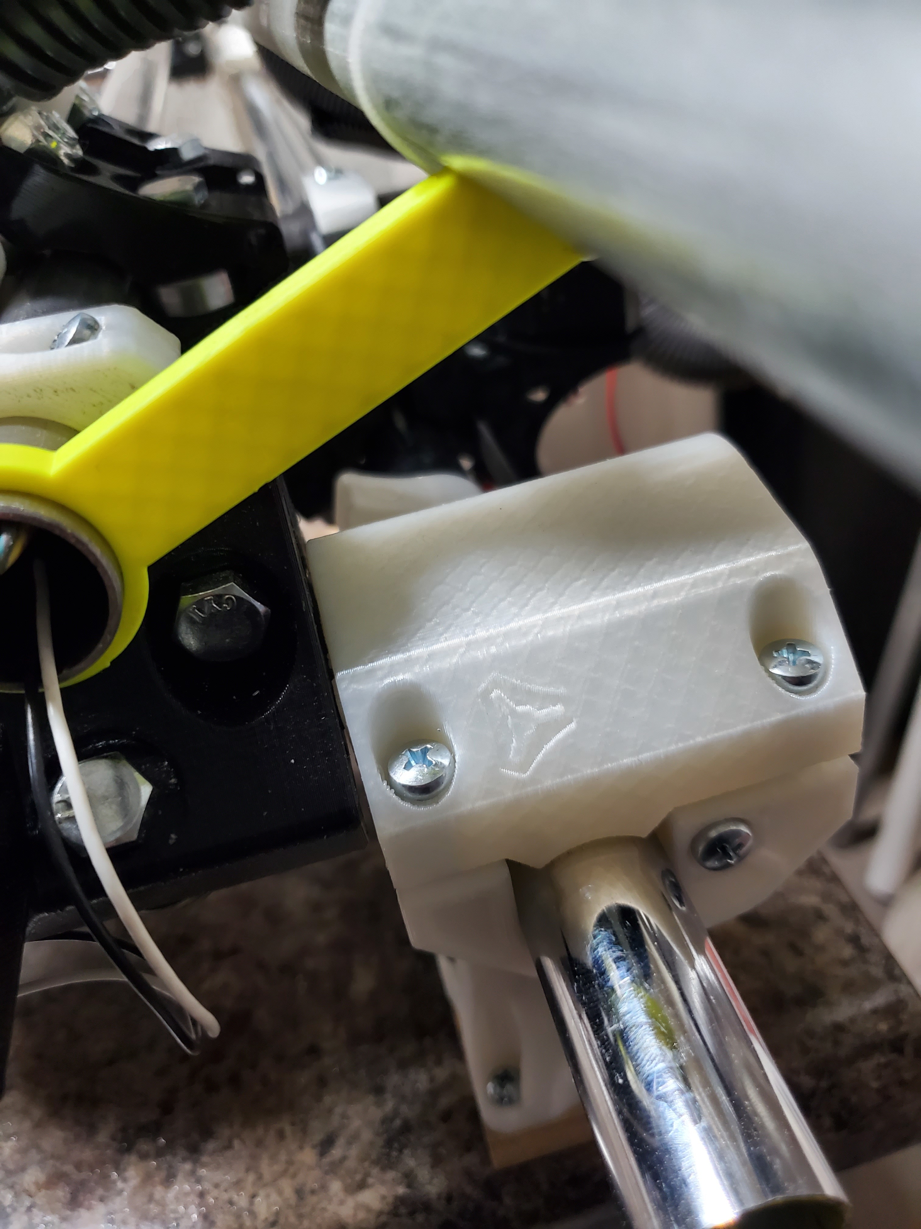
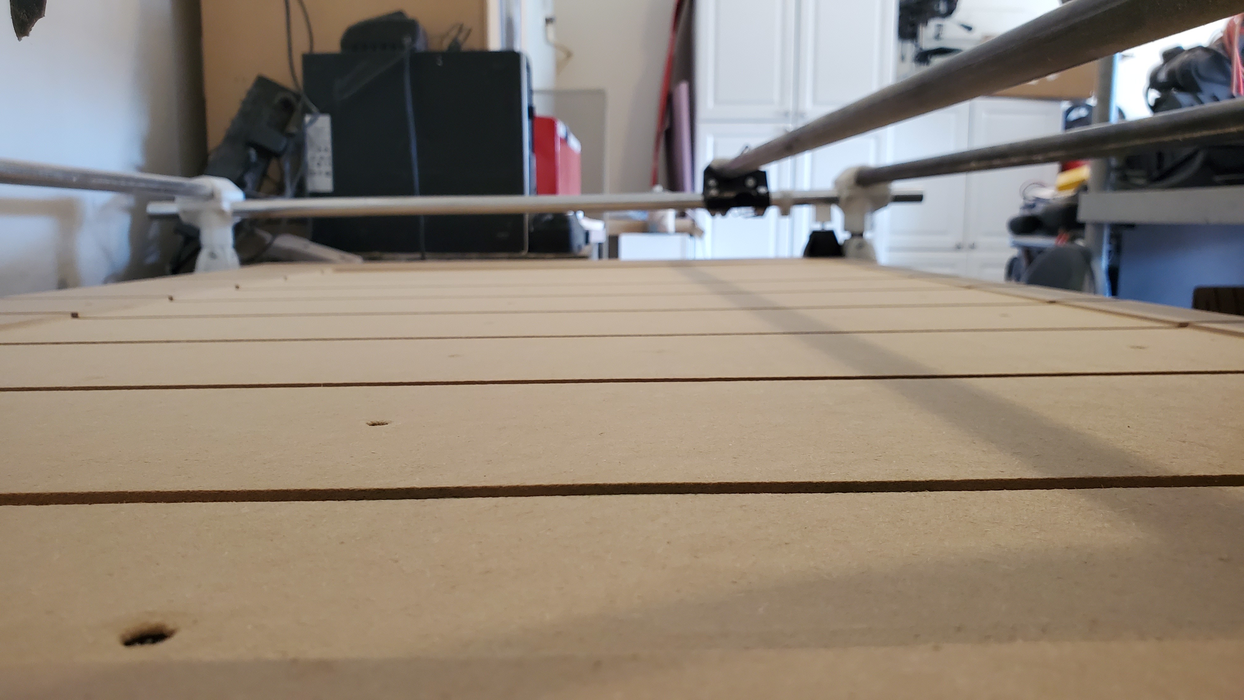
Ended up with this :


You can see the front right leg there on the right. Came up a bit. The front left is out of view, but also to the right. It came up about half that much. Both rear legs on the left remained unadjusted.

I don’t really understand how anything I did during construction could bring the leg mountings that far out of the plane, but thinking about it, 3 points define the plane and maybe that corner is just too low relative to the other 3. Actually, that makes a lot of sense. Probably could have shimmed under the desk right there. I’ll have to go see if it’s missing the foot.
Now, 1) when I send it to zero anywhere on the surface, it’s actually at zero, so that’s good and 2)since there are no ridges, I presume the tool is perpendicular to the surface in both directions. If 1 and 2 are actually true, then I really don’t care about anything else, I think.

Since the work area is so large (2x4) I only have one or two jobs that tile, and those aren’t through cuts, so I’ll raise them up to cut. Everything else fits easily (so far). I’ll probably lift up anything that through cuts on some mdf. The stuff I’ve measured all seems to be +/- 0.02in.