Randomly I am getting the probe triggered. I know it must be some electrical interference coming from somewhere, but it is very hard to trace.
All cables are shielded and grounded and I have ferrite beads on most cables.
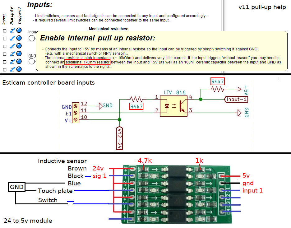
Would putting a pull up resistor between the positive line and the trigger pin help as the trigger is activated by shorting down to ground? If so, what would the best value be?
I am using a Nano for the controller.
I have the same problem with my tickets touch plate ghost triggering. I just disable it, I mostly don’t need it.
My other sensor that often triggered had a bad connection.
I think I will try adding a pull up resistor and see if it helps or not. Maybe 10K should be safe enough.
Hi,
10k would be fine, could drop to 2k2 or even 1k if you need. Typically 5V signals can be affected by electrical noise spike. I would recommend also adding a 1 nano-farad (1nf) capacitor across the input and ground. Place it at the board end and try and keep the leads less that 20mm. (not super critical but shorter is better. If using a cable and connector I just crimp them in with the leads and connector.
Mud map below -

Yes Tim, that is what I had in mind. The capacitor is a good idea to add as well.
I will do that soon and see if it makes a difference.
I did it on all 7 pins that I am using. After testing for a few hours I didn’t have any issues so far, but as it happens randomly it may still happen, but I don’t think it will.
Here is the type of board I am using.
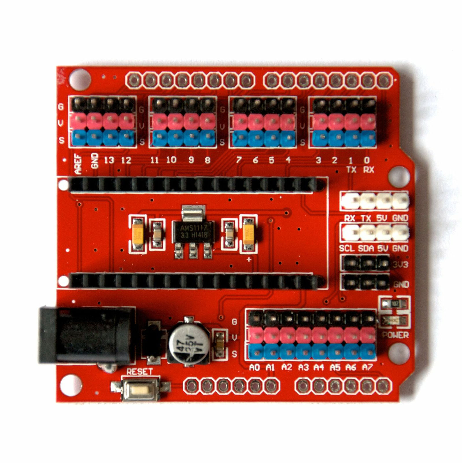
It makes it very easy to wire up for Estlcam.
I made seven plugs like this.
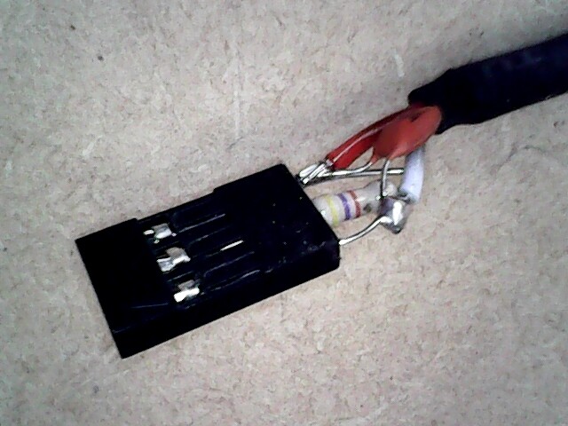
I insulated them all so the connects don’t touch as there is little room between them all.
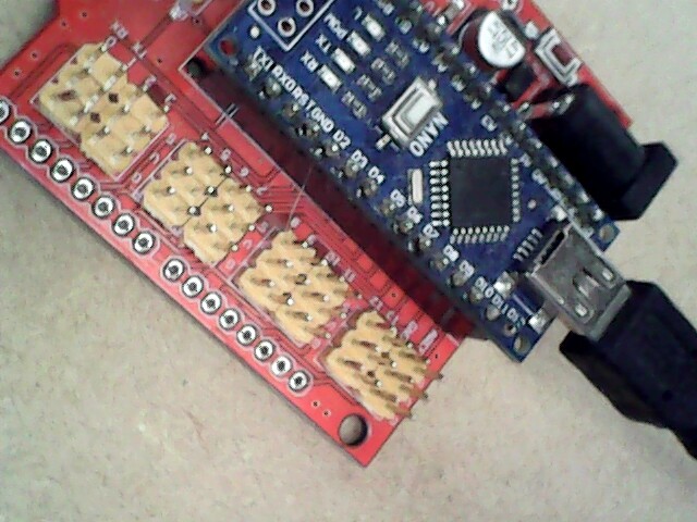
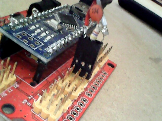
Just one shown plugged in here, with them all plugged in it would be hard to work out what was what.
I put a label on each cable so that I know which pin to plug into for in the furure.
2 Likes
That’s the way. Fingers crossed going forward.
I assume you’ve encased them in heat-shrink to avoid shorts.
I tried some heat shrink for that reason, but found it was too thick, so I ended up using clear tape. I used clear so I could identify the orientation of the plug.
1 Like
I used the machine all day yesterday and again this morning. No false triggers so far, seems like it has fixed the problem.
I will do the same on my other machine that sometimes suffers from the same problem.
1 Like
Glad to hear it.
Now that I know it works, I have designed a small PCB to fit onto the Nano board that will make it neater for all the input and output connections. I have already sent the files off to China and should get the boards back in a few weeks.
Using the cable connections worked, but was very untidy and hard to fit it all together as there is not much room between the connections.
1 Like
Estlcam recommends starting with a 100nf capacitor and adding a 1k pull-up (v11 help, v12 has no pull-up option/help) if random input triggering persists. While I have had no issues using just a 10nf capacitor for some years now, I’ve just switched to optocouplers on all inputs (motivated by the addition of an inductive Z limit switch)… Added a momentary start/pause switch (to drawing and machine),
Thanks for that info Dave.
I have PC817 on the limits for isolation, the limits have given no problem.
The false triggers have been on the button inputs, pause, run, stop, zero axis. I have a button switch for each of these functions.
After fitting with a pull up and capacitor on each input the problem went away.
On one of my machines I am having a problem that is different. Almost every time I go to use it, the program V12, freezes in exactly the same place no matter which CAM file I am using.
It always stops at the line marked bolded every time.
G00 Z5.000
(No. 1 Hole machining: Hole 1)
G00 X0.053 Y0.120 Z5.000
G00 Z0.500
G01 Z0.000 F100 S24000
G01 Z-0.500
G01 X0.031 Y0.130 F250
G01 X-0.004 Y0.137
When this happens I have almost no control over the program.
I can use the software buttons to activate the outputs only, I can’t close the program down, I can’t stop the spindle that is going flat out, the pause button doesn’t work and the only option I have is to use Alt Control Delete to call up the Windows task manager and close Estlcam down that way.
I don’t know what is causing this to happen, but possibly when I fit the pull ups and capacitors on that machine it may not happen any more.
When it happens I may have to try again a few times to get the job done, but once it has passed that line of code it will continue to the end without a problem. This happens too often on that machine, not everytime, but more often than I would like.
While the stock board works (use tested) as originally presented, it appears that the only only reason the 1k pull-ups and 5v input need to be there (when using Estlcam) is for the LED’s. I’m now wondering if the Estlcam board inputs only have 4.7k pull-ups, if the internal ATmega pull-ups are only enabled on Arduino boards. The following (via SMD removal and jumper wires) works fine so far.

Glad it works. The combination of internal and external pull-ups seems less than ideal. Sorry, no clues on what might be causing the lock-ups on your other machine.
1 Like
While I am waiting for PCBs to arrive, when I have some time I will try doing a big job like a 3D carving again, and see if there are any hiccups after I have made this change. The tests so far have been good,
My other machine that has the lockups and freezing problems I have decided I will build a new controller from scratch. I still want to use that machine as it is solid and reliable apart from these freezing problems. Once it gets past that first cutting line of code it runs to the end most times without a problem.
Maybe some clues here. Pity that no circuit is shown and the Arduinoclub site is down.
It looks like power to the optocoupler is 6v through 220 ohm resistors (VS my 24v through 4.7k) and that the output makes the connection between the Nano input pins and ground (same as my last image).
The Estlcam Terminal Adapter is different in that it has 4.7k pull-ups on the processor input pins. My guess is that they are used in place of the processor internal pull-ups (guaranteed to be between 20 and 50k) that Estlcam enables on generic Arduino boards.
1 Like
My new machine has 12 volts (separate supply) for the optocouplers and the limits, and my old one worked fine with only 5 volts which is below the recommended voltage.
I will be rebuilding that controller soon anyway, so I will probably use 12 volts again, although I will be using a 24 volt supply so maybe I can do the same as you have done.
FWIW (only static tested), an optocoupler with just a 4.7k resistor on the input and a 4.7k pull-up on the output/Nano input works in v11 with or without the internal pull-up enabled.
…Looking at the Estlcam board setup page (Estlcam: 2D / 3D CAM und CNC Steuerung...) it looks like I was wrong, the 4.7k external pull-ups are used in tandem with internal pull-ups by default. Also on that page is the recommendation to use 24v unless something (e.g. relay or solenoid) needs 12v.
While external pull-ups (1 - 4.7k) are typically not required, they do insure reliable switching. The only thing that my removal of components from that optocoupler module did was remove that insurance.
I am in the middle of wiring up a 24v system now, so I will keep that info in mind.
One of my other controllers I noticed that in hot weather the processor would shut down and I would have to wait a few minutes and press thye play button again, it continues on without any problem.
This new controller I have added some 80mm fans and a thermostat with the probe under the Nano board. Tested it out and I have it set to come on and off at about 25C and it works fine.
Testing in summer when it is over 40C here will be the test, the fans will be on at the start up.