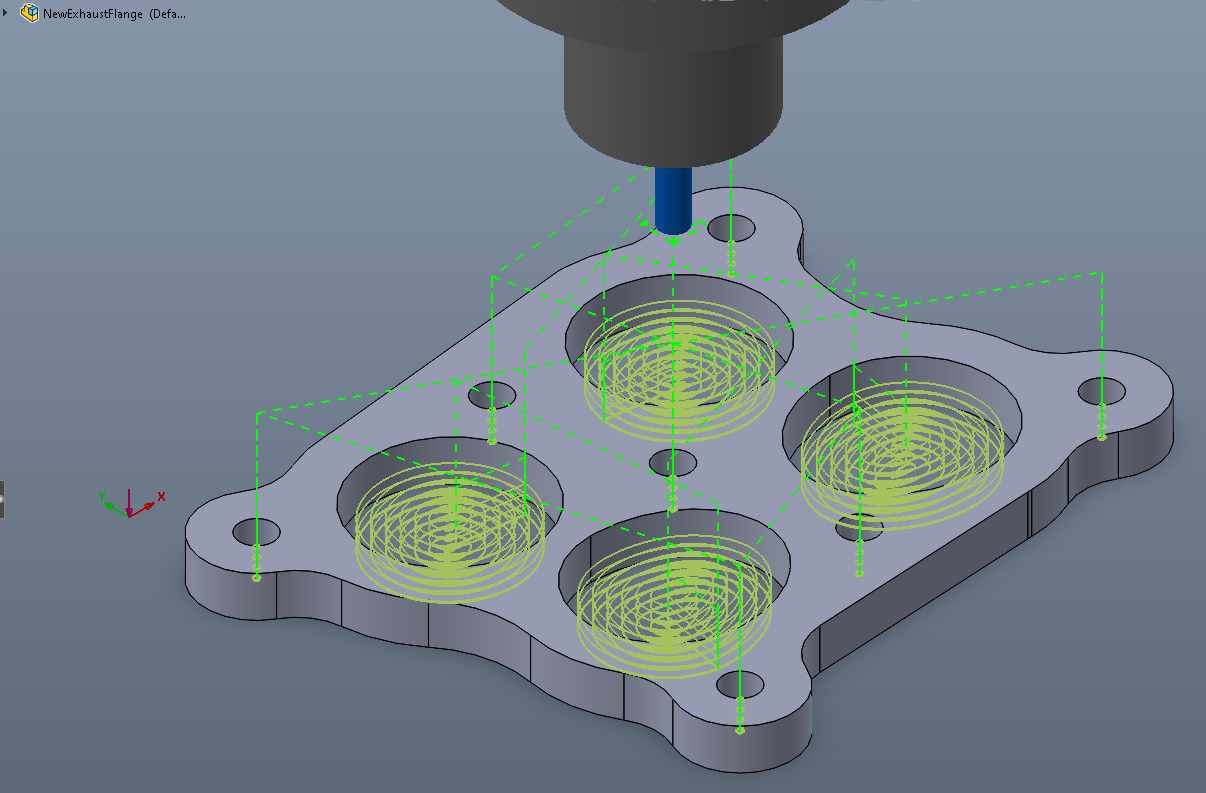
I too am struggling to get SW to do some of the more simple things that Estlcam does very well. Likely because I am not a machinist, just a dumb engineer. lol. One of the challenges I have is figuring out how to “layer” the operations in SW to be able to use things like support tabs, that are only available in a 2D contour cut. i.e. machine everything except where the tabs are, then machine that area. Otherwise it just machines away the tabs. I had same trouble learning F360 as well. In Estlcam this is pretty easy even for 3D carves.
Anyway, attached is my source for the SW post processor. You can use it directly as is and the output is pretty Marlin friendly. NOTE. You cannot use any drilling features in SW CAM. It outputs codes that Marlin does not know. Also, my tool change is specific to how I do it, but it is editable (either after post or you can relatively easily edit the post processor code and recompile it with your own). Finally it relies on Marlin for rapids (G00) speed. I guess most CNCs assume this is controller based. I reset mine in the firmware (discussed here):
To use as is:
-
Unzip to a local folder the you will use to work on the post processor.
-
Copy the following files to C:\ProgramData\SOLIDWORKS\SOLIDWORKS CAM 2020\Posts (or equivalent for your install):
MPCNC.ctl
MPCNC.lng
MPCNC.pinf (defines the output file extension)
MPCNC_S.rtf (short description in SW CAM)
MPCNC_L.rtf (more or long description in SW CAM)
-
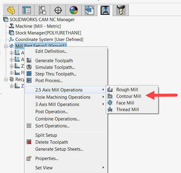
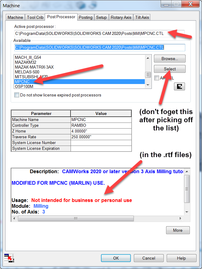
Restart SW, and in SW CAM select the post processor in the Machine Setup (note it must be a Mill-Metric and SW units have to be in mm).
Here is a sample of the output:
;
;O0001
;
; ( PART NAME=Alternate9l4_NoMag_SnapIn-LockRing )
;
G17 G21 G80
G54
G92 X0 Y0
S5000 M03
G90 G00 X46.059 Y52.946
Z28.424
G01 X46.075 Y52.985 Z25.572 F560.
X46.136 Y53.132 Z25.174
X46.237 Y53.377 Z24.837
X46.364 Y53.686 Z24.597
X46.631 Y54.333 Z24.424
X48.803 Y59.598 F700.
X50.358 Y58.982
X57.838 Y57.046
X67.33 Y54.888
X79.391 Y52.888
X93.344 Y51.523
X105.251 Y51.064
X117.138 Y51.291
X128.18 Y52.093
X134.757 Y52.962
X135.723 Y53.428
X136.471 Y54.155
X136.969 Y55.106
X137.185 Y56.442
X137.096 Y122.169
X136.976 Y122.535
X136.855 Y122.9
If you want to change anything in the post, it is best to edit it in the source file (MPCNC.src) using EC-EDIT-2 and not in UPG-2. The latter will muck around with the code layout and makes it harder to track your changes. UPG-2 can be downloaded from here: https://camworks.com/universal-post-generator/. It comes with EC-EDIT-2.
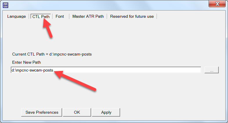
Before recompiling, make sure you set the output of UPG-2 to your chosen folder for editing the post. In UPG-2, use File-Preferences and change the CTL Path to your local folder:
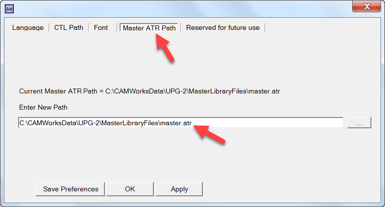
and make sure you have it pointing to the Master ATR Path in your install folder:
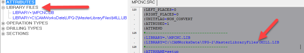
Finally, open the MPCNC source file in EC-EDIT and verify the Library section points to the install MILL.LIB file (the one included in the zip file is a reference only) :
The only files that need to be updated after recompiling are the .ctl & .lng files. Copy those two into the SW CAM posts folder above (overwriting the previous ones). You have to restart SW to recognize the new files, or in Machine Setup dialog, select a different post (any one on list), then re-select MPCNC, then hit the Select button before closing the dialog. Big PIA.
As mentioned my tool change script is specific for me. You can edit it in the section called SUB_TOOL_CHANGE_MILL and SUB_PRELOAD_TOOL_CHANGE_MILL (I believe both need to be populated and for some reason I think it is only the latter that is called, though it shouldn’t be by definition of PRELOAD). This is what mine looks like:
:SECTION=SUB_TOOL_CHANGE_MILL
:T:<N>;=====start tool change<EOL>
:T:<N><G!:53>                             ;change to machine coordinates<EOL>
:T:<N><G:00>X25 Y25                         ;move to tool change position<EOL>
:T:<N><M:00> turn off router             ;confirm router off<EOL>
:T:<N><M:18> Z                           ;release z<EOL>
:T:<N><M:00> tool: <TOOL_COMMENT> ;confirm tool installed<EOL>
:T:<N><M:00> z-probe                     ;confirm probe is installed<EOL>
:T:<N><G:28> Z                           ;probing<EOL>
:T:<N><G:00>Z30                             ;raise off bed<EOL>
:T:<N><M:00> turn on router              ;confirm router is back on<EOL>
:T:<N><G!:work_coord>                             ;change to workpiece coordinates<EOL>

*
:SECTION=SUB_PRELOAD_TOOL_CHANGE_MILL
:T:<N>;=====start tool change<EOL>
:T:<N><G!:53>                             ;change to machine coordinates<EOL>
:T:<N><G:00>X25 Y25                         ;move to tool change position<EOL>
:T:<N><M:00> turn off router             ;confirm router off<EOL>
:T:<N><M:18> Z                           ;release z<EOL>
:T:<N><M:00> tool: <TOOL_COMMENT> ;confirm tool installed<EOL>
:T:<N><M:00> z-probe                     ;confirm probe is installed<EOL>
:T:<N><G:28> Z                           ;probing<EOL>
:T:<N><G:00>Z30                             ;raise off bed<EOL>
:T:<N><M:00> turn on router              ;confirm router is back on<EOL>
:T:<N><G!:work_coord>                             ;change to workpiece coordinates<EOL>
NOTE: Syntax matters heavily in the code. All the :T:'s,bracketed EOL’s, etc. mean something and must be correct or the post will crash. If you make changes to the file in EC-EDIT, use UPG-2 to compile only. Do not open the file in UPG-2. Under file, use the Compile Source option. Not file open (at least not until you become familiar with what UPG-2 will do to your code sections).
MPCNC_Post_230221.zip (98.4 KB)