Please don’t apologize… it wasn’t clear in my post what I meant. But I was referring to an earlier post, where Jeffe suggested to wire it to one of the end stops.
I’ll have a look in the firmware to see if I can find something.
Please don’t apologize… it wasn’t clear in my post what I meant. But I was referring to an earlier post, where Jeffe suggested to wire it to one of the end stops.
I’ll have a look in the firmware to see if I can find something.
IIRC, the actual pin value is set in the pins file. But you also need to enable it in the configuration_adv.h. I haven’t done it in recent versions.
Hi everyone, I am super happy with my MPCNC and I always have some new project to cut, so I am thinking to improve it a little bit.
In Italy we use to say: “L’appetito vien mangiando” (Appetite comes with eating)
I was just looking for information on how to turn the spindle on and off from the Ramps, when I found this post.
My electronics are based on Arduino Mega with Ramps 1.4.
I was thinking of connecting a 12V relay to the D9 terminal (Who in a printer will power the print fan)
The question are:
1 - do I need to make some changes in the firmware configuration? I hope not…
2 - Which commands should I insert at the beginning and at the end of the gcode to turn te spindle ON and OFF ?
Time ago I was asking how to setuo the Z offset to compensate 5 mm thickness of a touch plate. (Define Z offset 5mm in FW)
Since I dislike to edit the firmware I inserted in ESTLCAM the string G92 Z5 as suggested by Jeffeb3, so I get it automatically at the beginning of every Gcode. Thanks Jeffeb3
Any suggestions will be appreciated
Thanks
Paolo
To turn a fan on and off use g-codes M106 and M107. I’m guessing the fan index for the M106 command will be 0, but it might be 1.
So to turn the fan on:
M106 P0
and to turn it off
M107
You should not have to make any firmware changes. These codes can be added to the program start and program end scripts in EstlCAM.
Many thanks Robert,
I will follow your suggestion
cheers
Paolo
Oke I opended my pins file and I would like to connect the relay to the Z Max pins, here’s what it says:
#define X_MIN_PIN P1_24 // 10k pullup to 3.3V, 1K series
#define X_MAX_PIN P1_25 // 10k pullup to 3.3V, 1K series
#define Y_MIN_PIN P1_26 // 10k pullup to 3.3V, 1K series
#define Y_MAX_PIN P1_27 // 10k pullup to 3.3V, 1K series
#define Z_MIN_PIN P1_28 // The original Mks Sbase DIO19 has a 10k pullup to 3.3V or 5V, 1K series, so when using a Zprobe we must use DIO41 (J8 P1.22)
#define Z_MAX_PIN P1_29 // 10k pullup to 3.3V, 1K series
If I look here:
https://marlinfw.org/docs/configuration/laser_spindle.html
It say the following:
Alternatively, you could configure the following to use M3, M4 and M5.
In the pins_MYBOARD.h file for your board make sure the following pins are defined:
#define SPINDLE_LASER_ENABLE_PIN xx   // digital pin
#define SPINDLE_LASER_PWM_PIN    yy   // digital pin - MUST BE HARDWARE PWM
#define SPINDLE_DIR_PIN          zz   // digital pin
I don’t see those lines in my ‘pins_MKS_Sbase.h’
You also need to enable laser or spindle mode (in configuration_adv, I think).
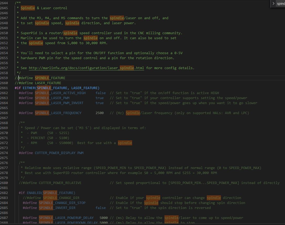
yes here… I can uncomment line 2659 in the configuration_adv file
But I also need to do define the SPINDLE_LASER_ENABLE_PIN in the pins file, but I can’t find the line.
Can I add it?
The laser is enabled in the SKR_Pro Marlin firmware that V1 maintains. Because of the way their tools work for maintaining multiple versions, they added the following in the top of the configuration.h (rather than the pins_???.h) file to enable the laser support:
#define SPINDLE_LASER_PWM_PIN PC9
#define SPINDLE_LASER_ENA_PIN PB0 // Heater2
You should be able to put these defines in either place (configuration or pins). I’d pick the one that would be the easiest to maintain if you need to merge these changes in when updating to a new version of Marlin.
If it were me, I’d take the configuration.h, configuration_Adv.h, and the pins_ files and do a diff between the SKR_Pro firmware and your firmware to see the differences. Something else might popup.
Thanks for the reply!
So if I understand correctly I can add this line manually to the pins file?
#define SPINDLE_LASER_ENABLE_PIN XXX
I’m not an expert, but it should be fine. This define is in the pins file for the Rambo board.
Edit: With these defines, usually all that matters is that it is defined before it is referenced in the code. So if your code compiles, you are good to go (this assumes you have enabled the code that references these defines).
Yes, you can just add it. Make sure it isn’t already defined. These files can be tricky, because they sometimes include another at the top and then just add a few differences.
Oké! So this is the edit I did in the pins file:
#define X_MIN_PIN                          P1_24  // 10k pullup to 3.3V, 1K series
#define X_MAX_PIN                          P1_25  // 10k pullup to 3.3V, 1K series
#define Y_MIN_PIN                          P1_26  // 10k pullup to 3.3V, 1K series
#define Y_MAX_PIN                          P1_27  // 10k pullup to 3.3V, 1K series
#define Z_MIN_PIN                          P1_28  // The original Mks Sbase DIO19 has a 10k pullup to 3.3V or 5V, 1K series, so when using a Zprobe we must use DIO41 (J8 P1.22)
//#define Z_MAX_PIN                          P1_29  // 10k pullup to 3.3V, 1K series
I commented the Z_MAX endstop.
//

// M3/M4/M5 - Spindle/Laser Control

//

//#define SPINDLE_LASER_PWM_PIN                 45  // Hardware PWM
#define SPINDLE_LASER_ENA_PIN                 P1_29  // Pullup!
//#define SPINDLE_DIR_PIN                       32
Is it set correctly for a Makita RT0700C by using the ENA_PIN? I just want to enable and disable, no PWM.
There is a significant chance the change you made here will not compile. If it does not compile you will need to comment the Z_MAX_PIN define and assign it to some unused pin on your board.
It didn’t fail on the Z_MAX but something else, I can’t figure out what…
    c:/users/bambi/.platformio/packages/toolchain-gccarmnoneeabi/bin/../lib/gcc/arm-none-eabi/9.2.1/../../../../arm-none-eabi/bin/ld.exe: .pio/build/LPC1768/src/src/feature/spindle_laser.cpp.o: in function `SpindleLaser::init()':C:\Users\Bambi\Documents\MPCNC\Firmware MKS Sbase\Marlin-1CNC_Rambo_Dual/Marlin\src\feature/spindle_laser.cpp:56: undefined reference to `set_pwm_frequency(short, int)'
collect2.exe: error: ld returned 1 exit status
*** [.pio\build\LPC1768\firmware.elf] Error 1
================================================================================================= [FAILED] Took 596.17 seconds =================================================================================================

Environment    Status    Duration
-------------  --------  ------------
LPC1768        FAILED    00:09:56.172
============================================================================================= 1 failed, 0 succeeded in 00:09:56.172 =============================================================================================The terminal process "C:\Users\Bambi\.platformio\penv\Scripts\pio.exe 'run'" terminated with exit code: 1.Oh, that looks familiar. I think this was fixed in a recent version of Marlin for the Skr Pro board. Something about that specific pin didn’t have PWM defined or something.
Thanks Jeffe, do you know the solution?
I’m using the Rambo dual endstop version as my base and with your help I altered it to work with my MKS Sbase board.
It’s using Marlin version 2.0.5.3.
I see the newest version of Marlin is 2.0.7.2
I promise, I would have told you if I did.
Yes I believe that 
Does this help?:
Oke so I loaded the original ‘Rambo dual endstop’ folder in VSCode.
First I compiled it with nothing changed… that worked.
Then I edited all the things I did when I first configured my MKS Sbase board, that worked too after compiling for the second time.
After doing the spindle+laser edits, I get the same error message.
I don’t know what to do next…
Oke… I donwloaded the latest ‘Marlin-bugfix-2.0.x’ and I made all the edits myself so it’s the same as the(/my) ‘Rambo dual endstop’ version.
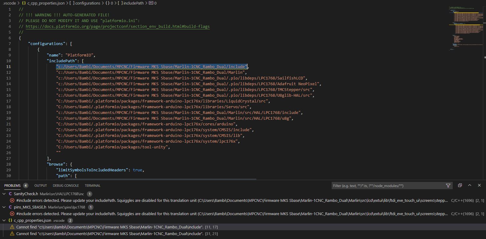
The problem is I can’t compile, I get 1 error:
    In file included from Marlin\src\lcd\dogm\marlinui_DOGM.cpp:46:
    Marlin\src\lcd\dogm\dogm_Bootscreen.h:40:12: fatal error: ../../../_Bootscreen.h: No such file or directory
          |            ^~~~~~~~~~~~~~~~~~~~~~~~
    compilation terminated.
    Compiling .pio\build\LPC1768\src\src\lcd\dogm\status_screen_lite_ST7920.cpp.o
    *** [.pio\build\LPC1768\src\src\lcd\dogm\marlinui_DOGM.cpp.o] Error 1
    =============================================================================================================================================== [FAILED] Took 12.92 seconds ===============================================================================================================================================

    Environment    Status    Duration
    -------------  --------  ------------
    LPC1768        FAILED    00:00:12.923
    ========================================================================================================================================== 1 failed, 0 succeeded in 00:00:12.923 ==========================================================================================================================================