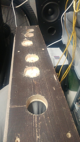
Those are speed holes!
this wasnt a time for cnc, i have daily meetings where my phone is overheating and killing its battery and my machine would have taken alot longer to do this i think. Maybe Maybe not. I think it would have taken me and my machine longer than me and my pillar drill.
Absolutely. I was making an obscure reference to the simpsons:
Speed holes, I like it.
photo heavy post but i will explain.
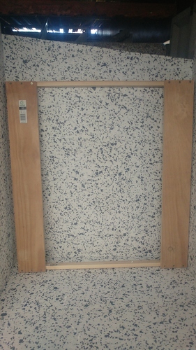
this was the outer frame that previously sat on the Ikea table i designed it for. unfortunately it is pine and not ply so it has warped in the heat inside my garage which has a metal roof. This was i think the major but not only source of my out of level bed. I have decided that I am going to just screw direct into the Ikea table. It’s not in great condition but it is flat and i will not be planning to use it again as a dinning table, we have since bought a much nicer one on the wife’s orders.
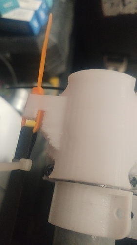
this is the replacement for the corner which snapped at the screw holes which happened when i tried to move the whole mpcnc but didn’t have a good stance and one of the legs came down harder than it should have at an angle on the table. i am working in a room too small for the project and the rather large polystyrene box that is my first attempt at sound proofing is hampering movement in the already cramped office.
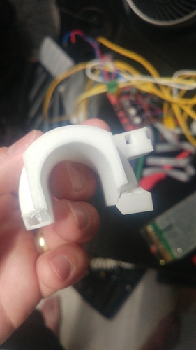
the was the offending broken piece. I noticed i had bugger all fill in there so little wonder it broke. was a nice print though. Compared to the functional one i replaced it will (100% fill, 1 mm nozzle and 60 mm/s speeds) which was done in one hour.
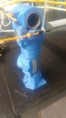
next is my attempt at raising the legs and simultaneously getting them all the same height. I figured I needed a spacer and had this leg corner bottom part which was an erroneous mirrored overprint that I made when I printed all the originals. Using this and the broken white top above I went round all the foot pieces with a thin flat router spanner to pry them apart increasing the height and now they are all pretty damn similar.
hopefully when my 3Dtouch (cheap BLtouch clone) arrives and I have a nearly level surface now, I will enable bed leveling and be able to get a far better end product. It already looks better on the black surface.
The current state of the Lavington avenue CNC. Note the server PSU repurposed for driving the ramps board.
Just did a little test of getting the bit just above the surface of the Ikea table and doing a large perimeter rectangle of the cutting area to check to see how flat we are or whether a leg needs shimming. The bit dug in toward the flat corner so we make have a candidate for a thin coke can shim for the furthest leg in this photo.
Learnt lots today, i decided to play around again in fusion 360 as its where i design all my plastic printed things and it would be good to be able to go straight from there rather than estlcam simply because making hybrid parts which are composed of both additive and deletive? processes would be far simpler.
Anyway at first i looked into feeds and speed for wood and getting the mill tool setup. then i looked at the post process part which gave me an nc file, then i spent a chunk of time looking into nc to gcode converters and used one on github palinhob which was written in python. This was far too simple and not really upto the task as all it does is parse the lines and puts in g0 g1 and f* on each line and doesnt take out stuff thats not marlin specific. I looked again on google and had better google foo this time as i found martindb’s contribution which is a cps file (a fusion post processor file) so you can just export straight to gcode.
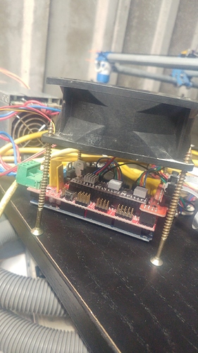
I also upgraded my cooling solution with is a 12v 1amp server fan running full tilt. (need to drop the V with a few zenners or add a real speed controller.
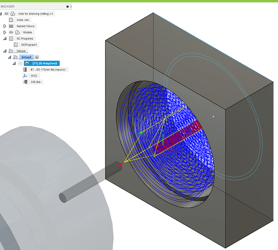
Anyway i learnt abit more todo with creating better looking tool paths and i like the simulate tool in fusion better. Ive run a few of the passes without the router running and with now material in the way just to check that the post processor isnt making the mpcnc behave badly but it seems ok so far.
My latest idea is a reuse of some shelf legs.
I bought a about 6 sets of shelving which was to sort out the storage in my garage. I put 3 of each either side of the same wall but the only just fit if i modified them such that the inner shelf shares its legs with its two outer neighbours. The upside here is that i have 4 spare sets of legs. I just need to replicate the hole in the plastic shelves into some wood. This is essentially a 5mm doc circle 39mm which captures the smaller diameter of the leg and a 41mm circle to pass through the rest of the shelf/wood concentrically. My plan is to upcycle some floor boards so i don’t have to chuck either out.
waiting on some more bits that i ordered before i do any more ornate stuff.
this was the fusion simulation which is nicer by far than the estlcam view. Estlcam is good for simple but i would have to be far more organised keeping track of the files.
argh, so the hole is too small. by a full 5% the small diameter should fit the 39 mm of the plastic tube but its milled to only 37mm (cant be much more precise than that as i need new batteries for the vernier calipers)
anyway i recounted the number of teeth on my x/y pulleys, 16 i looked up on the prusa calculator for the 32nd stepping at 1.8 degree per step and it comes to 200 which is what the firmware has on a quick m92 check.
Could belts stretch account for this? is it just my poor gcode. not getting the tool settings correct?
scratching my head on this.
Unless the belts don’t have any reinforcement, they don’t really stretch that much. Add a finishing pass and see if that helps.
I tried to redo all the belt tensions as per v1engineering.com/belts and listened for a bass guitar note (would be helpful to know which note). But now i am having more issues of skipped steps. Getting frustrating but maybe fix this and look into finishing passes. Thanks Barry
One thing i noticed is that as you cut close to the rails you have part of the belt very highly tensioned and the other part alot looser. Not sure how to solve this problem. The upshot is it is easier to cut quicker in the middle of the gantry where the belt tension is similar either side of the roller.
Tension should be the same on both sides.
Just reread the bloody instructions and i did it wrong. I was rushing but i got the idea now. Very annoying when its user error and you yourself are the user.
The new version of the docs are here:
https://docs.v1engineering.com/mpcnc/belts/
That looks to me like it has the same information, but if there are any changes needed, we will make them to the new docs.
It exactly the same content but looks nicer. I cant tell where my stiction is coming from. Could be the rails no parallel enough or the belts. Its just becoming this moving target. I think also i am maybe pushing the limit on the cuts sometimes
The instructions look nice. I hadn’t noticed the “best practice” step before. I might have to re-do my belts this weekend.
Just found a source of my error in the fusion output. The stock to leave by default comes as 0.5mm which is really 1mm over the diameter so that could totally be all of it. Just need to get my machine cutting nice again now i messed with all the belts.
Losing steps cutting against the grain. Maybe i should be doing the test cuts in ply to remove the bias.
How fast are you cutting I could not find your reference but start at 500mm/min aprox and see
Try 2 mm to start and see what it will do then slowly increase
Okay so @timonjkl was right 500mm/min is a much happier place to start at 2mm level doc per pass.
This is my nth attempt now at creating a hole with a small lip inside to catch the profile of the plastic legs i have left over from my garage shelving.
I found the fusion 2d circular cut which for my geometry is the same as a contour. I split the job us into 3 lots of gcode.
1 a straight down central 20mm doc drill
2 a 15mm doc 41mm contour
3 flip the work and recentre the bit on the hole created in 1 as best i could and do a 5mm doc 39mm hole
conclusion. this thing is getting borderline useful. btw i say that we the me at the helm, i think with a seasoned pro this machine will be very useful.
just cutting the contour beats the hell out of trying to cut the whole thing out in 2d adaptive pocket creating a shit ton of shaving each time.
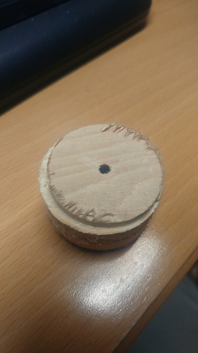
you can see from the part which came out my reposition of the bit over the hole wasnt perfect.
from a test fit of the plastic leg the 39mm is loose but good enough the 41mm is a smidgen to tight. easy to fix.
This concludes today’s efforts.
