Slowest UK MPCNC build, South Manchester, in the Shed on Lavington Avenue

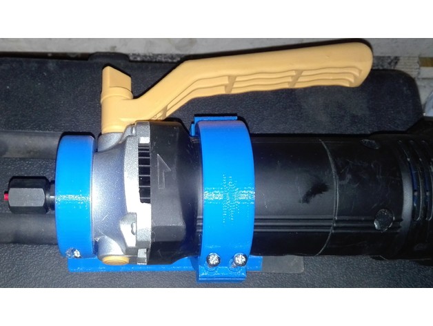
I made this mount and shared it on the facebook group its pretty robust with the original back plate on the 25mm kit.

mckeller mount

thing on thingiverse

This is for the mckm28 600w router by Mckeller, which is one I already had and didn’t fancy shelling out for another.

It has 3 parts, two of which can be printed twice to add more support at the top but honestly I don’t thing it will be necessary.

If you do use this please bump this thread so I know how many people this has helped out.

So reprinted the top rear twice and front one once so now I have two top mounts as I originally designed it to have. Through over tightening the rear bracket piece snapped. The new parts are in black pla since I ran out of the original blue. I actually ran out part way through printing the last of the four legs but managed to manually swap the filament mid print pausing my anet a8 and it worked fine. I upped the speed on the mounts to 150 which was 3 times the 50 it was at for the mckeller mount parts here and my printer appeared to cope. There were more imperfections but liveable for what it needs to do. I had a disaster though when I came to place it back into the centre gantry, the bottom bracket part snapped on the right hand side so that the right bottom rail guard only has three bearings attach now. I tried to glue it back but I think the epoxy I have doesn’t work on PLA. Will just reprint the part but really slow and max fill.

In other news I am making sure my 3Dprinter and MPCNC has a proper home in the form of a garden office. Took a couple of days off and dug a hole and poured some concrete for the foundations. Here is my dog helping dig and the result so far.

[attachment file=32106]
[attachment file=32107]
[attachment file=32108]
[attachment file=32109]

Hi,

From what I see on the pictures, you clearly have a major extrusion issue.
My guess it that your nozzle is partially clogged.

You should take it apart and clean it, hopefully it will solve your problem.

Other tip: superglue works perfect to fix broken PLA parts.

you may well be right on the extruder. I am just coping with it at the moment since its dialled in right for the autoleveling, I have a e3d hotend clone which I intend to swap in soon and external mosfets to allow the hotbed 24v to heat quicker. And I intend to do a Bowden extruder as well but since its mostly working I’m just making sure I finish all the parts for the mpcnc first. Will try again with super glue too. the stuff I used is good for acrylic but I think it makes the PLA weak. I might have ruined it already with my first botched rescue attempt. Will give it ago but its not a massive hardship to reprint it.

My printer really needs a bit of tlc but time and apathy when it mostly works is really self defeating.

tried super glue (cheap knockoff) didnt work, going to print slow tonight, i have 40mm/s and higher infill dialed in so hopefully i will have a stronger piece this time. dont really want to tear down my anet a8 printer just yet to clean it up. I have a replacement nozzle i can use maybe i should do that at the least.

well I reprinted the lower part of the middle assembly in black, printer calibration was way off so consequently it lifted at the back while printing and may be a bit out but the print completed and it fit together okay so its all back together again in my temporary office in the house. After that i did recalibrate my printer properly. I designed a box for my dcdc bst900 which i use to charge my electric emax scooter. That print was pretty good, no lifting and a good first layer. Will start improving the printer with the e3d hotend and external mosfets for the bed and hotend and use a 24v supply. just need to print all the required bracketry for it and maybe buy a different inductive sensor since the mounting of the cylindrical ones is easier to calibrate and fit.

I moved the concrete walls for my new external office on to its foundations, I am a couple of weekends work from having a permanent 24/7 runnable location/final resting place for the mpcnc, till then im a little less than committed in finishing it as i cant run it in anger till i have the office outside done anyway. There is a little person in the house im am not allowed to wake with my projects.

Its tempting to get the MPCNC plotting with a pen i.e. finish the electrics but too many other jobs too
little time.

Did some CAD work in fusion to work out how to use the old sectional concrete with the existing garage. There is a visible raise where the new foundation is poured so you can tell what is old and new just by looking at the step up in the wall nearer the back.

Anyway here is a teaser. tempting to print this out to help aid construction when i have a team of people to do a walkthrough of the build first.

[attachment file=32700]

So I have had to reprint both the ends of the middle array as both broke in the same way. The replacements were in black with the original in blue. At least there is more symetry to it and the fill was increased to help prevent it snapping again.

In other news I made the first stud walling for my office (which will house my MPCNC) The are actually the triangles for just below the roof and they have taken me 3 days to build. However the MPCNC came in handy as I was able to use it as a MPMC as in mostly printed manual control. in that i dont have the motors installed yet but clamped the x and the z axis and used it as a railed trim router on some brackets i hadnt cut perfectly. So its dirty and its not even fully assembled.

Anyway its made me really itchy to get going on it as i can see how much easier my life would be contructing things with this than with most my other tools.

Stag do abroad next week, but once im back from that I will be all about the MPCNC again.

That workshop is looking cool. It reminds me of Frank Howarth’s mammoth shop. You’ll have to name it, and then carve a sign for it. :slight_smile:

I have mine in my garage, but my 2.5 yr old will sleep through it, once he’s actually out. I just get the complaint from my wife when I slam the garage door, but he sleeps through anything.

So i was supposed to put up the rest of my office walls last saturday, but the rain poured all morning which meant the mastic for between the panels was never going to stick. Anyway this made me go away and think about the application of 25 or so tubes of building mastic with a hand squeeze sealant gun. At the best of times its horrible getting a consistent bead with these so i decided i would be better off designing my own.

Basically it is based on the z axis in that it has a 6mm threaded rod and long nut build into some plastic printed end caps which go into some drain pipe with will hold the sealant tubes. (i had excess lying about and a template from my ramps box design already. I will couple the threaded rod to a cordless drill and use the speed setting to extrude a consistent bead onto my concrete panels. thats the plan anyway. just waiting for next weekend and a bout of sunshine.

[attachment file=35679]
[attachment file=35680]

This is to allow my m6 bolts to grip to the chaffered concrete panels, thats is providing a good flat surface.
[attachment file=35681]

the next two things are for grabbing the 48.3mm OD scaffold pipe (using 3 of them) on each side of the stud walls with a single small screw and a cable tie through all 3 to grip to the pipe.
[attachment file=35682]

this one i created using a sample of Element by ntopology. i have a trial 90 license but since my paternity leave is 3 months thats a nice fit. I tried printing this mesh but the results were a bit disappointing. i think the liquid/uv based 3d printers would cope much better but it was a bit of a torture test for the anet a8.
[attachment file=35683]

Cool projects and the space to do them in, that makes is so much more fun to do. You have some design skills and you think outside the box. Interested to see how this looks when it is done and how the new tool works for you.

1 Like

[attachment file=41588]
So quite a bit of down time. We have been very busy. My office has walls and a roof and a shiny set of 2nd hand solar panels. just waiting on a call from my electrician to come tie them into the grid. Nice to see it looks like my cad model. Anyway the office bit is still full of scooters/emax mopeds and other such stuff but i need to level the floor with some leveling compound and line the walls and the ceiling but im really getting there now and then my mpcnc will have a proper home.

So I’ve finally moved my desktop PC into the new office from where I’m writing this post. The wifi even seems to reach despite the rain. I laid a nice cheap laminate floor after leveling it with about 11 bags of floor leveler. That’s about 220 kg of the sealant powder over a few days. Next thing to make it in here will be the MPCNC but the rain is pouring so i will wait for that to end first (i could be here a while).

Also on Friday my electrician installed the inverter and generations meter so i am now feeding solar back into the grid. Annoyingly the meter doesn’t smartly send back the reading every quarter and relies on the owner to do that so I am tempted to sort out a system to automate taking a picture and emailing it back with a time stamp so that i don’t forget and lose out.

Will post some pics of the office/workshop when i have moved the other stuff in.

Still haven’t finished my router but I went in the office the other day to trouble shoot some stuff. basically my Z axis was really wobbly which was having a bad effect on the plastic supports. turns out my issue is that the stepper motor axle is 4mm but the threaded rod is 8mm and my couple was just a straight through 8mm to 8mm which meant it was eccentric not concentric or egg beater esque which was vibrating the shit out of the z axis. I have a 4 to 8 mm coupler on order from china and will start again on this when that has arrived. Few things to reprint due to this issue.

WARNING LONG RAMBLING POST
Covid19 has meant I am now remote working. after a 2 year hiatus where my two boys, wife and dog have kept me suitably busy I am now sat by my MPCNC which has languished here for almost 3 years in my office at the end of the garden.

Anyway, over the last few days i did an assessment of what was left and began making some decisions. I think when I downed tools on the MPCNC, I was going to try dual stops and auto squaring straight away but hadn’t really finished the wiring of the steppers. I am using cat 5 for the wires but using two strands per half of a stepper phase. This hopefully double the current handling as cat 5 wires are very thin.

Yesterday I figured out the right hand rule for my particular build and wired it up as parallel x and y (not auto squaring, baby steps now) and I’ve tested that the axes all move in their respective correct directions from home +Z being into the bed and the rest dictated by the right hand rule.

Unfortunately due to poor plastic choices, a previously badly calibrated Anet A8 3D printer and worst of all, alot of ultra violet light over time coming through my shed window many of the parts are cracking. especially those which hold the z axis rails. they are not that strong especially when you forget that and are trying to release a router bit which was a bit jammed in without going to the trouble of sliding the z carefully out of the gantry by undoing the coupler (everything is 2020 with hindsight).

My 3D printer currently has a 1mm nozzle in it as i was printing some aero infills for my Nissan leaf by Paul Kennett. I don’t know if i should just try and reprint these broken bits of the gantry again. my MPCNC is a mishmash of original Cura default blue, bad black PETG (i think it’s PETG , it never printed nicely for me) and more recent white PLA which is good stuff and was before i switch from a 0.4mm to a 1mm nozzle.

I bought some cat 5 sockets which are for SMT to PCBs. They were cheap and i bought some breakout boards which made the soldering of the stepper wire easier. I didn’t have enough of these breakout boards and then today realised coming back to it after two years that the male header pins for stepper wires have the same pitch as the pins on the bottom of the cat 5 sockets. This meant using a bit of white tac (to hold the fixture whilst soldering) I was able to complete the wiring without the PCB breakouts and it’s probably even neater.

Being that it is such an old build i still have the old threaded rod for the Z axis and not the leaded rod that the newer builds use. i need to tweak the software settings to get back my z scale so that 10mm on my motion on the ramps board makes the router bit actually travel 10mm.
If anyone knows what the old settings are or can point me to the file with them in that would definitely help.

Cracking plastic aside, I think its not far off a test crown. To do anything with the actually router i may have to reprint some the the gantry and work out the z scale issue. Not a million miles off now. I feel like I’ve been in a race where i was one of the first to start and might still be the last to finish.

If anyone is still following this build thread any encouragement will be welcome. I don’t know how to change the title which has become very misleading due the change in focus over time.
You can adjust it by moving and measuring. I remember them being a weird number in the ballpark of 4500 steps/mm. But I think that is for 1/32 microstepping.

You got this. The “regulars” here can change a title. What would you like it to be?

Thanks Jeffe,

I think the most sensible thing would be to take the 2nd post onwards into its own thread. Please rename it to:
“Slowest UK MPCNC build, South Manchester, in the Shed on Lavington Avenue.”

much appreciated.

will measure the z move with a digital vernier and do the math to scale it

1 Like

:white_check_mark:

I also moved it to the builds section.

Is this a typo? I think everyone assumes +X to the right, +Y away from you, +Z is up/away from the bed.

1 Like

ok, maybe i have it wrong, that was the hidden reason for posting it.

Will re-read the setup section. I guess i would find out in my first cut when it decided to come off the bed rather move than towards it. I am going to take this very slow as I am really new to cnc albeit having about 4 years of 3d printing experience and more in 3d design.

Thanks for the move @jeffeb3 Jeffeb3

You should certainly go at your own pace, but these things are pretty forgiving. You can certainly “learn fast” while “moving slow”.

Here are the docs I wrote about the coordinate frame. Right hand is key, but I think +Z=up is a really good idea:

https://docs.v1engineering.com/learn/coordinates/#coordinate-directions

You’re well equipped to climb the learning curve. You’ll find there are several places where you’ll have to just push forward, despite not having exactly the information you need.