At least I did something right!
1 Like
FIXED IT.
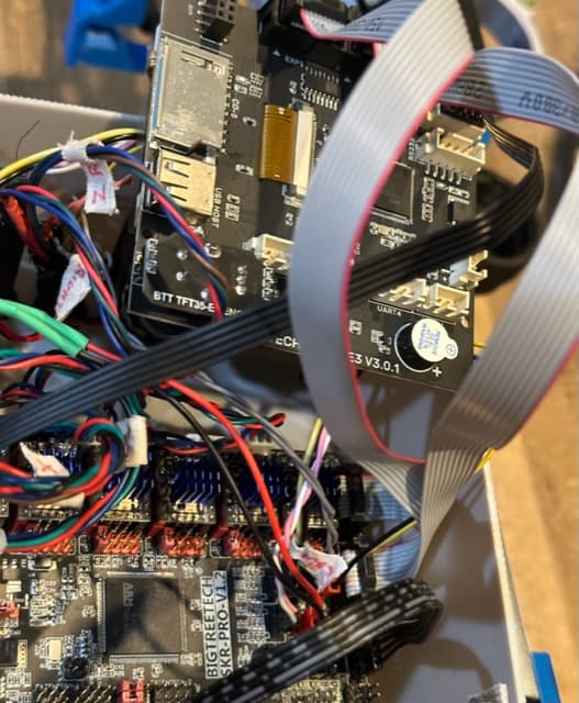
I took the black cable off to make sure all the cable/connections were good from end to end using an ohm meter. Everything checked out OK. As I went to reinstall the cable I checked documentation and plugged it back in and fired it up - It worked! However, I new that was just too weird. I looked at the pic I sent you and the black cable was plugged into the SWD connector instead of the RS232 connector on the TFT35. I pulled it out of the box and installed that way ![]() . Just another lesson I have to relearn again. . .
. Just another lesson I have to relearn again. . . ![]()
I am sorry that I used so much of your resources on this. I also want to say thank you again for the help, I sincerely appreciate your time.
4 Likes
Shoot I missed it right here.
Howard,
I am trying to troubleshoot a similar issue that you mentioned. I have 3 SKR Pro boards with several problems as you described. I want to try to reflash each of boards as a starting.point. I will boot them with all wires disconnected and just the USB cable.
I need help with understanding the firmware procedure.
I have tried the MPCNC Skr pro firmware bin file on a 8mb chip. I can’t get them to load and change the file type. Some times the touchscreen works, and Marlin doesn’t even respond. Neither one communicates with the steppers. To start over: what is the exact file I should load on the startup chip?
Are there any step by step instructions for testing boards?
If I mounted the boards on metal stand-offs do the top and bottom pc board connect and cause electrical problems?
Should the 3vt led always be on when the 12 vt cable is connected?
Any comments would be helpful.
Thanks
Rand
For flashing the firmware, there is a jumper for the 5V power to take it from the 12V supply or take it from the USB. by default this takes power from the 12V supply. If you are trying to flash the firmware connected with USB, then this must be in the USB position. Otherwise, it will work when the 12V power is connected.
When the 12V supply is connected and the jumper is on the 12V supply then it is normal for the 3V3 power LED to be on whenever the 12V is connected. Actually in that case, all three LEDs for power should be lit.
I have mounted my SKR Pro on metal stand-offs, but try not to mount them where they can connect to something else. There is a copper ring around the screw terminals that is connected to the board ground. This can cause a ground loop which will pick up EMI interference and can cause some issues with some of the board functions. The top and bottom plane of the same board should be okay, there are already several points where they connect, and the screw holes are considered safe that way.
I have used the documentation on V1 Engineering’s site. Here is a link to find the correct bin files: SKR Pro - V1 Engineering Documentation. This link will take you to GitHub and all the bin files are listed there under assets, there are 37 different files. Once you download the correct file you will need to unzip it and copy the unzipped contents to your SD card. I can’t tell you exactly what file you need because I don’t know what machine you are building and the options you are using (for example: dual end stops or not). This is the easy method, otherwise you can compile your own bin file(s) - lots more steps!
Howard - I will explore the Github information and try to load the correct firmware.
I have the SKR pro set up with the V1 firmware. I want to use the extruder signal to drive a paste applicator stepper motor but it sends an error that the temperature is not correct. I get an error that stops the cycle. Is there a code I can send to the firmware to turn off the thermistor or replace it with a 100 ohm resistor? How do I cancel the firmware checking the temperature? I have never changed code before so please explain the steps I should do… thank you
Rand
close older topics to help with spambots, and faster new user questions.