i’m building the MPCNC but i’ve encountered a problem with my stepper drivers. I had a bunch of nema 23 with the corresponding drivers and i don’t want to waste them on a shelf. It is possible to hook up the drivers to the board? if so i need some fancy electronic breakout or i just need a bunch of wires and cables? i saw some breakboards thoughout internet but i’m confused about the smd parts hooked on them.
Best regards.
P.S. i love the whole design of the machine, thanks for all the effort and developement spent on this amazing project.
Nema23 is a spec that defines the size of the motor case. Nothing else. The nema23 motors will not fit on a standard MPCNC. Given the fact that the correct sized motors are just over ten bucks in the shop, and they will work better than a nema23 in this machine, you should find another use for the 23s or sell them.
But I am not answering your core question. Most nema23s can use more current than our drivers can handle. You can connect then to the TMC drivers, but I don’t think that would end well.
Most drivers need an enable, direction, amd step signals. The TMC drivers use 5V for those signals. Your standalone drivers may use 5V, or 12V, etc. If that is the case, then you would need a level converter. But I can’t answer more without knowing exactly what drivers.
When using the kinds of boards that come across this forum for an MPCNC, in the few instances I’ve seen external drivers, I believe they bought or made something like this to export the pins necessary for external stepper drivers. And, as Jeffeb3 indicates, there are additional issues if your stepper driver cannot handle the logic level voltage from your control board. You also need to modify the firmware to match the stepper driver, though you can probably piggyback on the TB6600 settings in configuration.h.
As Jeffeb3 indicates, you will have to remodel some parts in order to handle the NEMA 23 motors.
I’ve already modified the rollers mounts for the nema 23. So the mechanical issues that comes with the enlarged dimensions of the motors are addressed.
About the drivers, on the z axis i still have a nema 17, as i said i want to recover as much parts as i can. The z axis motor comes with a DM542T stepper driver. The nema 23 (4 of them) are coupoled with 4 drivers DM542.
Both of this microstep( DM 542t and DM 542) drivers reports on the power side:
pul +(5v to 24), same for DIR and ENA.
All this material came from an old Arduino project where this drivers where driven by the arduino directly from the digital outputs.
Long story shorts: i need the breackout board, as Robert linked, from the SKR to the drivers or not? all my concerns comes from the lack of expirience with this kind of boards.
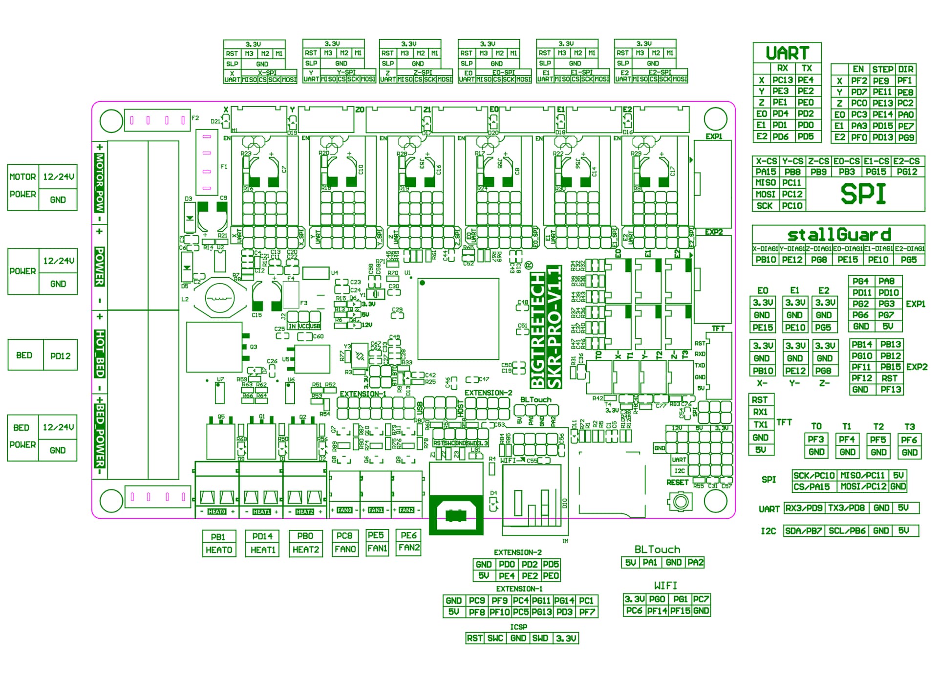
I have no practical experience with external drivers, just what I’ve read. I think you can just directly connect to the pins you need for each driver without the breakout boards. In pictures of these breakout boards, there are some resistors, but I’m guessing they are just pull-up or pull-down resistors since the board exports both pos and neg versions of logic (ena- and ena+ for example). If you just stick to the positive logic, I think you should be fine without these boards. My one concern here is whether the logic for the stepper drivers is 5V or 3.3V. The SKR Pro v1.2 is a 3.3V board, but, based on the pinout diagram, there is 5V on the board for some purpose. And even if it is 3.3V logic, many 5V logic devices work fine with 3.3V input.
If you are willing to wait for the breakout boards, you can get five of them from AliExpress for under $15, including shipping.
All you have to do is to remove the tmc drive module and connect the enabe and direction pins strin to d the board using wired pins. Also there is a jumper pind on the board to change d voltage from 3.3 to 5v.
Do you have a reference for these pins? I know there is some 5V pins on the board, but I’ve never run across jumpers to convert the stepper drivers to 5V logic.
Not yet. I’m happy with my arduino mega and grbl 5x with external drivers so i’ve installed the skr pro on my 3d printer. I’m running the machine with openbuilds control with my pc, i’m super happy with it.
If your custom machine is properly squared the auto squaring is not needed, but you can still manage to modify the mega5x grbl config file to add the feature while homing.
My hardware is: arduino mega, 5 external drivers, 5 microswitch 1 probe.
All the connection are done with an arduino Screw Terminal Block Breakout Module, MEGA-2560 R3
The standard one from v1 with dual endstops. I used dupont pin connectors (males) tomorow will send you a picture of where to plug them. You can also view your original stepper drivers they should have written what pin is what.
Thanks. I’ll need to modify the firmware then. Only need one x axis stepper. No need for dual endstops nor auto squaring. If the gantry is out of square, then something is bent or broken.
Hi Cesar, could you post the picture if you still have it? I am trying to figure out the connections with my SKR Pro v1.2 and DM542T external drivers for my CNC. The driver is not receiving any signals, so I am guessing I have the wrong pins plugged in.