Been chasing my tail for a while now with my SKR board, intermittently my limit switches won’t trigger, I know this is covered and I could probably deal with this but occasionally my motor direction will reverse too, I’ll press Z up and it will go down, reset the machine and it will go up when up is pressed, occasionally I’ll home any axis and it will go in the opposite direction. Are there any firmware fixes for this issue or should I just ditch the SKR and buy a jackpot?
Sometimes when I turn it on and make a movement in any direction it won’t allow me to make anymore movements after the first one (using the touch screen) until the board is reset
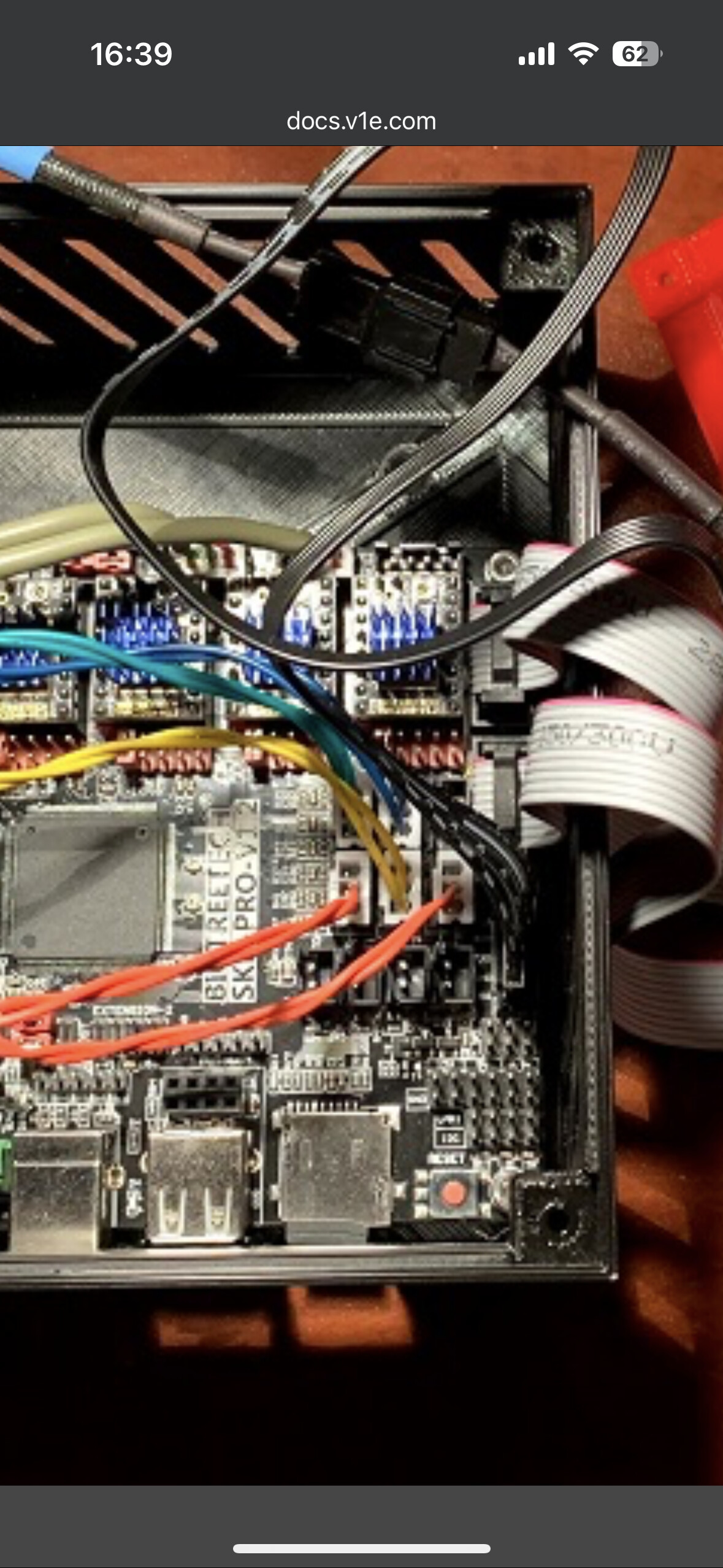
My wires are also causing me a headache on the board rattling loose, what have people done to solve this? Should I just solder the wires directly to the pins?
Where can I buy connectors for the limit switch socket on the board
The connectors on the motor wires and limit switch wires are normally Dupont connectors. (Edit - or at least the wires that come from V1E are, your connectors look different, hard to tell from he photo what style they are). Amazon sells them, usually as part of a kit with pins, sockets, and plastic connector housings that will hold either the pin or the socket. (you’ll need a crimper tool as well, can be bought either separately or as part of the above mentioned kit)
The black plastic connector on the board itself is a JST connector. While the Dupont connector “sorta” fits inside the JST connector, it isn’t a great fit, and can cause all sorts of connection issues. If you haven’t done so already (and I see that at least the unused limit switch connector still has it), they should be removed before connecting the Dupont connectors to the board. Grab the black plastic with a small pair of needle nose pliers and carefully pull them upwards (may need to flex them side to side slightly as you pull). This includes the motors as well as the limit switches.
Probably related to the Dupont/JST conflict mentioned above. Once the JST plastic is removed, people rarely have issues, but a small blob of hot melt glue could be used if desired.
Not recommended (IMO). That makes it really difficult to troubleshoot issues (reversing motor connectors to correct motor running the wrong direction on initial build, swapping motors between drives to diagnose issues, etc.). It is also pretty challenging to do so (lots of pins very close together, easy to solder bridge, difficult to access pins with a soldering tip, etc.)
This sounds like wiring issues. An intermittent connection to the motors will cause all sorts of issues. If the reversed direction happens when homing, it might be that the limit switch is showing as triggered (open circuit), and the motor is backing away from the switch iin order to perform the homing. Again, get all of your wiring connections sorted out first, and if it still happens, then let us know, and we’ll go from there.
That is a personal choice, lots of reasons to switch, lots of reasons to keep what you already have and get it working. We can help you either way you go, but wiring issues aren’t necessarily board specific, so let’s try to fix that first before you make a decision on the board.
Motors reversing position can also be due to solder work on the DIR pin of that particular stepper driver.
If it’s that issue, then we’d need to see high resolution pictures of the solder side of the SKR Pro for the socket where the driver is that reverses direction. Also high resolution photos of the TMC2209 driver itself.
I’d start by cleaning up the wiring as folks above suggested.
Apologies the photo isn’t mine, it’s one off the v1e website and I wanted to know what connectors they were so I could buy a kit as the Duponts just seem to be causing me trouble, Isit a jst xh connector kit I need ? So I can just plug them in and not worry about them shaking loose, am I right in saying the jst connectors “clip” into the sockets or are they just as bad as the DuPonts?
Iv tried pushing the DuPonts hard into the socket but feel like I am going to break the board, should the DuPonts be secured firmly into the sockets? Because mine aren’t at all
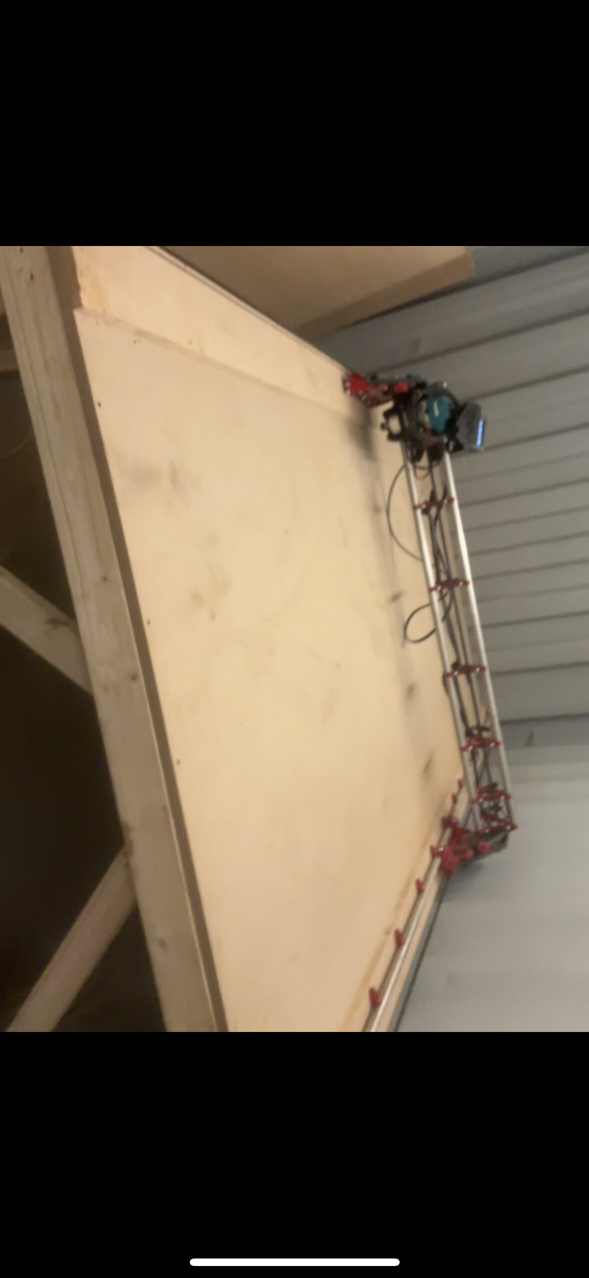
Thanks for the input will be trying to get this sorted asap, attached is a not upto date photo of the cnc (screenshot of a video )
If I remember right you can get a more positive connection from duponts by carefully prising the plastic sockets off the board leaving more length on the headers to push on to.
As I mentioned earlier, the Dupont connectors don’t fit very well into the JST connectors. Instead of cutting the Dupont connectors and replacing them with JST connectors, simply pull the black plastic JST connector shroud off with a pair of needle nose pliers ( as mentioned in the V1E documentation,)
I didnt know of the trick of pulling the jst connectors from the board.
When I was experiencing intermitent issues, i figured it was loose connectors, I used hot glue to hold the dupont connectors firmly it place in the jst spots.
figured I can always pick the hot glue out if i want to swap put boards etc.
Im very new to this, so dont know if what i did is advised. but it does seem to be working for me.
My own preference is to use jst connectors to attach wiring to the board. In all cases.
This gives you two things. In addition to the positive connection to the board, these are also keyed so that you can’t put them in backwards. (Especially important for the endstops. )
I also find the jst connectors to be much easier to crimp reliably.
I almost always do this by preparing a “jumper” with jst on one end and dupont on the other. This is especially useful for the motor connections as it allows you to reverse the connection if needed. (Power off, of course) Less necessary for the endstops since they have no polarity. They can be run all the way from the microswitch to the controller.
Now, for the jst connectors: you’ll probably want to get a kit. It will have both sockets and plugs, with various numbers of pins. The key thing is to get the correct pitch… they come in many sizes with only a few being commonly used. For this, you’ll want the JST-XH version which has 2.54mm pitch.
You’ll also need a crimper. There are many choices, from cheap and nearly worthless to professional grade. The reason is that there are actually two crimps needed on each wire… one on the wire and one on the insulation. Typically the crimper will try to do both at once. With a good crimper, this will work pretty well.
However, there is another crimper that allows you to do each crimp individually. This one is actually more versatile since it allows you to do both jst and dupont connectors (and even some types of spade connectors).
Now, some photos to complete this story. It should be noted that there are many options. These are the ones i have found to be successful.
You are correct at the micro switch end… the connection is just a contact closure.
However, at the control board end (at least for SKR controllers…I know nothing about jackpot. ) that is not true. You must use the center pin and a specific one of the others. If you use it incorrectly, it won’t work correctly and you can potentially damage the board, apparently.
By using the polarized, 3 pin JST with only the two correct wires, you eliminate this possibility.
There’s a reference to this which I’ll post of i can find out quickly.
Edit: it has been pointed out that there are two similar SKR boards that are commonly used for the LRx and MPCNC products. The pinouts in this post are for the SKR1.x class (not PRO). While the issue of how to connect the microswitch is the same in both cases (use G and S), the board layouts are slightly different and could lead to confusion. My comments regarding the layout are specifically intended for SKR1.3/1.4 users.
The important points are 1) use the correct schematic and 2) connect the microswitch properly.
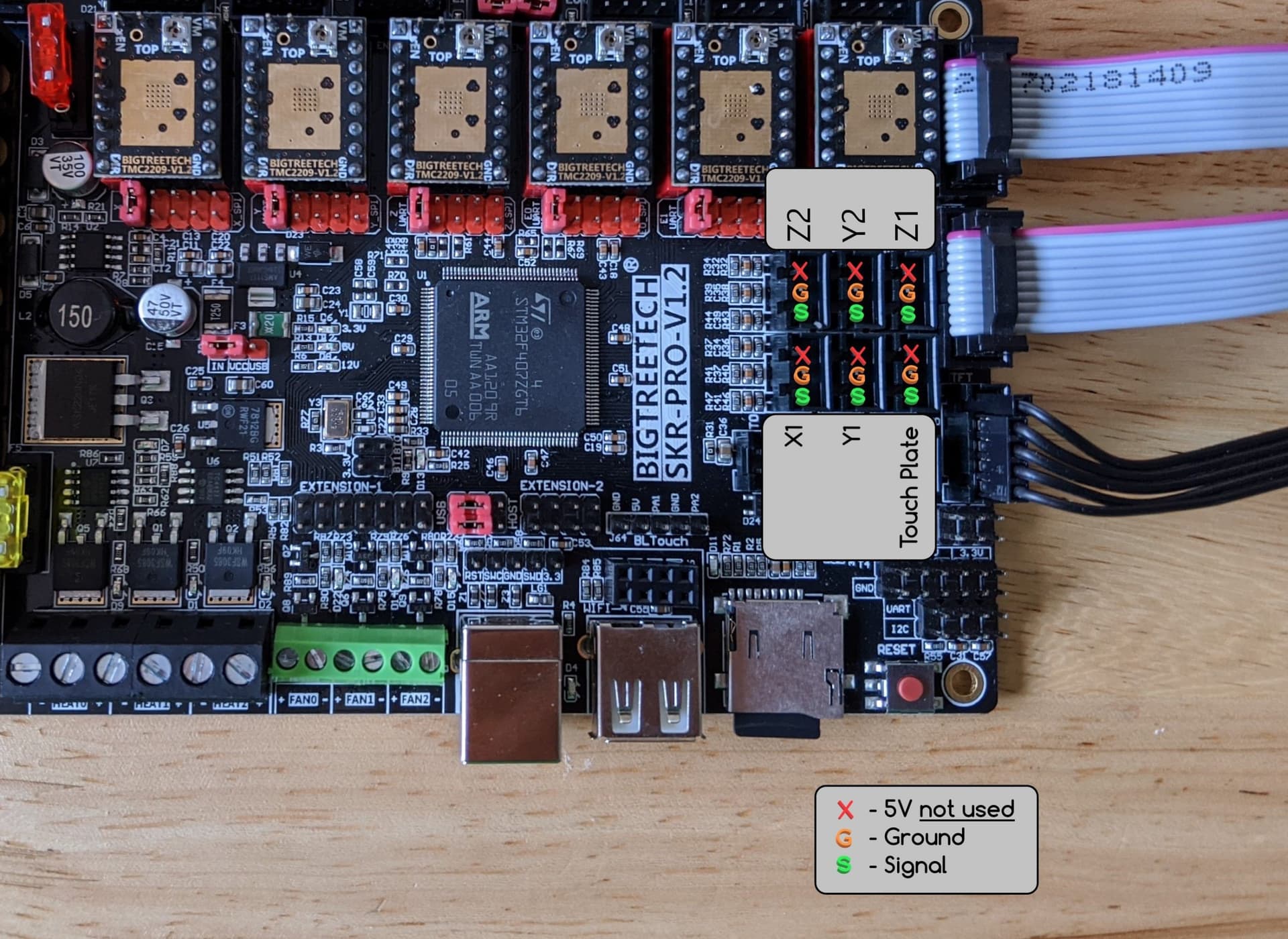
I can’t find the specific description of the issue, but you want to connect to the “G” and the “S” pins. I guess the “V” pin sources a voltage which you don’t want in this case.
For those unfamiliar with this issue, here’s the pinout from the SKR manual on github. There are also various youtubes, etc.
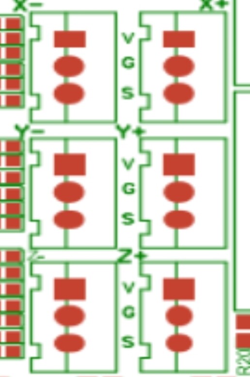
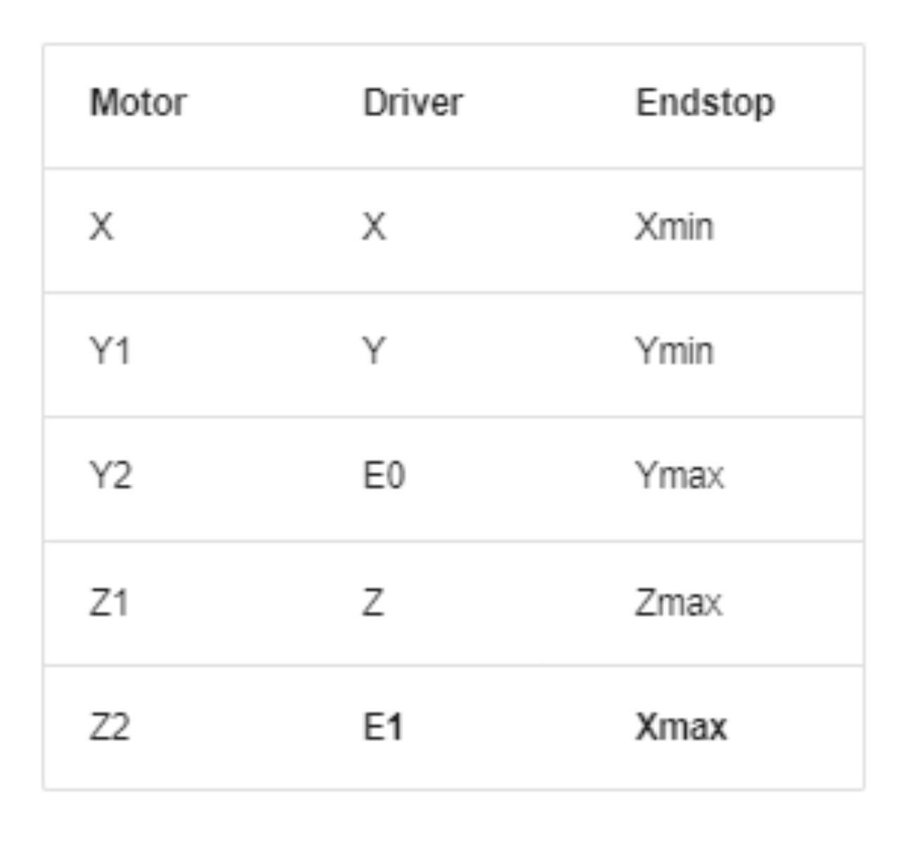
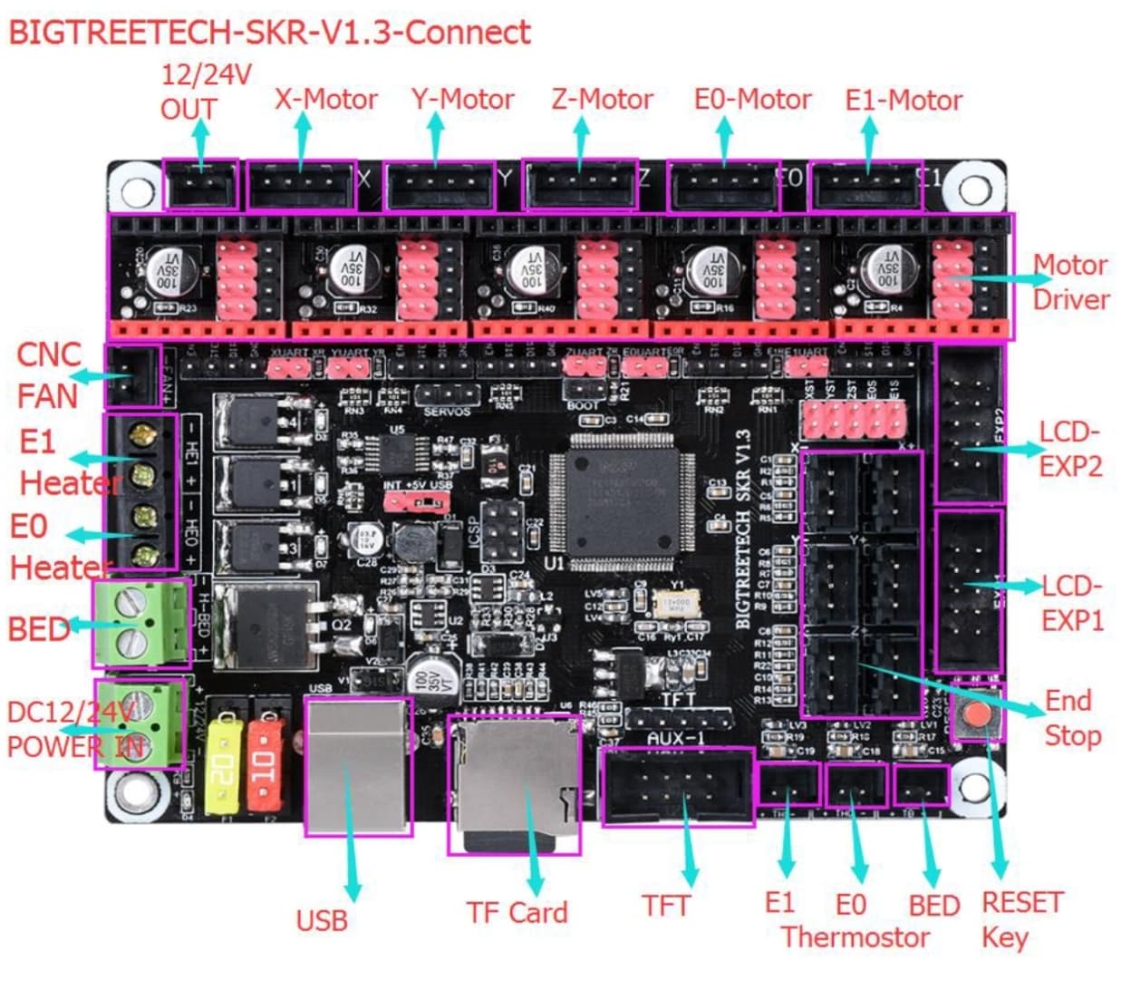
And, as long as I’m at it, here’s a diagram of the specific motor drivers and endstops for the LR4 using the SKR 1.3 (or SKR1.4?)
This is actually from the LR3 docs, but it can be the same if you use the same version of the firmware. Note that you should translate the “1” to “0” and the “2” to “1” if you are setting this up like the jackpot. (So, Y0 and Z0 are at the Xmin side and Y1 and Z1 are at the Xmax side.)
Obviously, this is specific to the SKR and related boards, but, I suppose there are many folks like me who are moving from a working LR3 to the LR4, focusing first on the hardware.
I’d actually recommend using whichever one applies to your board if you are not too familiar with setting this up.
Note that this image is specifically for the SKR1.3/1.4 board. While it’s similar to the various “PRO” versions, they are not identical.
The rotated connectors on your image left me uncertain which is why I dug out the actual manual. (Of course, what i SHOULD HAVE DONE is taken a photo of my LR3 setup which was working perfectly. )
Both your diagram and picture shows the SKR (not Pro) v1.3, which I think is relatively uncommon among V1E supplied boards. I believe that the board normally supplied by V1E is the SKR Pro (I think both v1.1 and v1.2 were sold, as the V1E documentation supports both).
I’m somewhat concerned that your diagram and picture may confuse some users that may think they refer to the common SKR Pro v1.2, and not the somewhat obscure SKR v1.3. Could I politely suggest that you edit both of your posts to clarify that they are for the v1.3, and not the Pro v1.2?
But I agree, it is important to use the correct picture for the board you are using
I’ve added comments as suggested. The original question was about the connection wiring of the microswitch and I happened to be asking the exact same question this morning and responded to the inquiry regarding polarity in more detail than needed, thus getting somewhat off track.
Hopefully anyone needing this info will be able to find what they need.