SKR Pro 1.2 LR Dual endstop issues

Good morning,

Finally taking the time to setup my SKR Pro 1.2 with dual endstop, and I’m running into a few issues

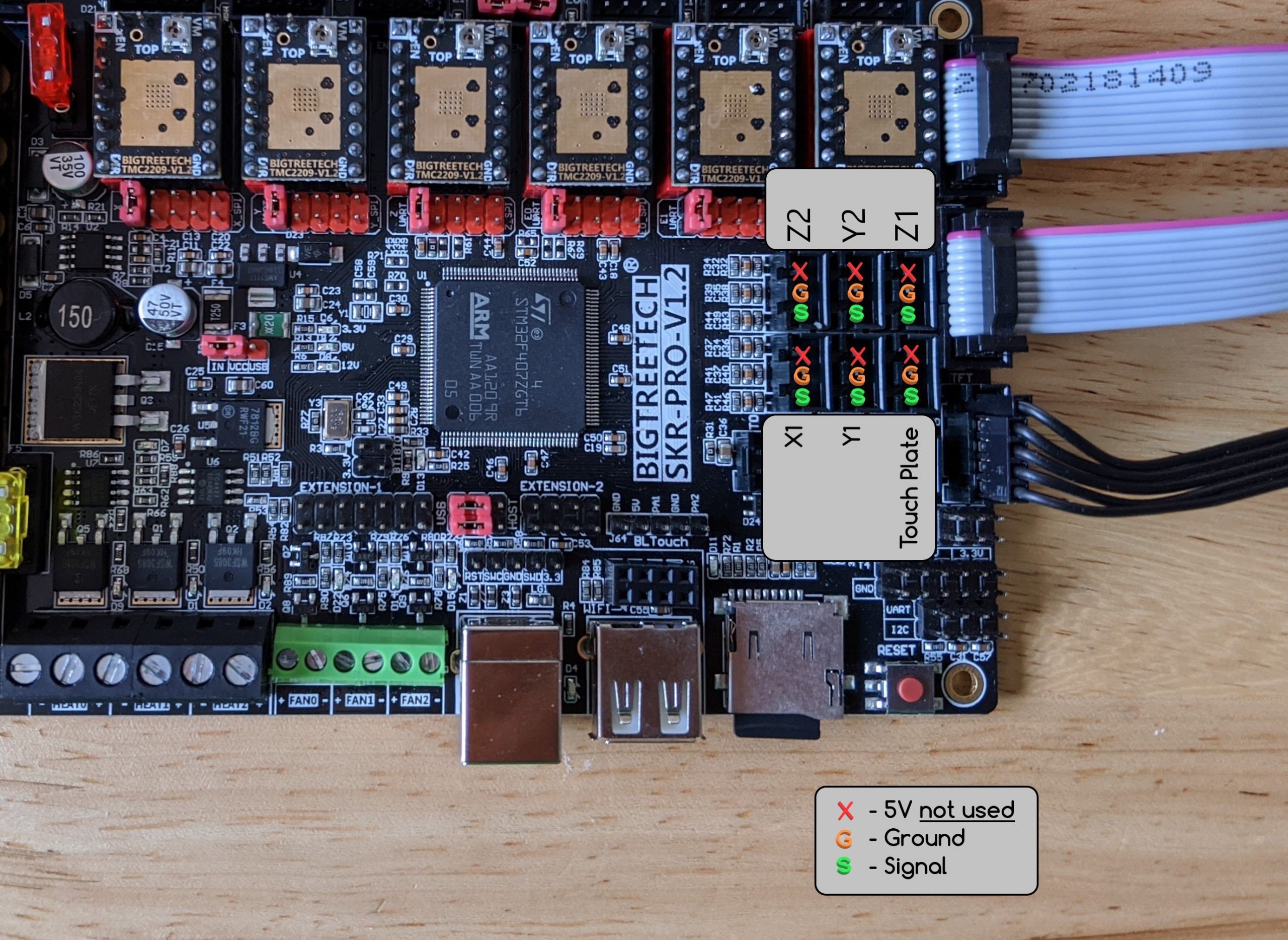
Note: for testing, I’m on a bench, with a dupont wire to simulate the switch, connected between Signal and Ground.

Using firmware from the main repo, ie:

SKR : github.com)]Releases · V1EngineeringInc/MarlinBuilder · GitHub
Touchscreen: Releases · V1EngineeringInc/BIGTREETECH-TouchScreenFirmware · GitHub

Specifically:
https://github.com/V1EngineeringInc/MarlinBuilder/releases/download/515/V1CNC_SkrPro_DualLR_2209-2.1.1.zip
https://github.com/V1EngineeringInc/BIGTREETECH-TouchScreenFirmware/releases/download/3-2023/CNC.TFT.Package.zip

I checked all firmware, and revision number matches in the info screen (both on controller board and TFT board)

1/ Am I right to assume that for a given stepper motor (let’s say Y), if the corresponding sensor is triggered (ie Dupont wire is removed) during movement, it should stop movement ? Because… well it does not… I checked with M119 command, and the sensor input is indeed triggering when removing the wire, and open when the wire is installed

But X movement does not stop when X is removed.
Same for Y

2/ Firmware description states :
V1CNC_SkrPro_DualLR_2209-*** *** Ready for dual end stops on a LowRider CNC (Y & Z axes).

Am I to assume that endstop are enabled only for Y and Z, or does this actually rather mean that DUAL endstop are enabled for Y and Z, and single endstop for X ?

3/ Using the above firmware for the touchscreen, I can connect, but when homing, I get a M420 “command not found” error. I’ve read into another thread that this is a known issue that can be fixed by firmware, but I tried the firmware provided in the thread, but I could not flash it (it did not flash itself)

4/ there is a warning on the documentation: " Do not use the + (positive) pins or you will ruin your SKR Pro board. "

Of course I think I just did that, since when testing I plugged the end of the Dupont wire to the + pin (so signal and + were shorted). Yes, my eyesight is not what it used to be. Could this really damage the input pin of the sensor (in which case I’m toasted), or could this be another issue (such as the pull up resistor sensitivity - knowing that the other pins are fine). I suspect it’s damaged, I would assume the input pin is 3.3V tolerant only, so shorting 5V to 3.3V was not a good idea… But that said it’s on the z probe, so that does not explain why the other signals are not triggering a stop (even though M119 does report a trigger)

5/ Looks to me the wiring instructions for the sensors on the documentation is odd… Specifically, it is stated that E0 stepper output should be wired to Y2, E1 output to Z2. But according to the picture for the sensor input (https://docs.v1e.com/img/LR3_endstops.jpg), Y2 sensor is wired to E1, and Z2 sensor is wired to E0, so aren’t they reversed ? Which one is correct, stepper output or sensor input ?

Comments welcome

Regards

There are 5 end stops. 1 for X, 2 each for Y and Z. This allows the machine to be homed in all 3 axes.

Shorting 5V to ground is a problem. Shorting 5V to signal isn’t Shorting 5V to ground does bad things to the voltage regulator, but the input pin is OK. The 5V source is there for active end stops, though we generally just use simple switches.

I can see how you would think that, but the end stop labels on the SKR board are also a bit weird.

The SKR board labels the end stops the same as the motors, but Marlin thinks of them differently. SKR labels X, Y, Z, E0, E1, E2 but Marlin thinks XMin, YMin, ZMin, XMax YMax, ZMax and makes assumptions about how they will be used. Wiring X Min stop to the X stop is fine. Marlin expects that to be an axis minimum end stop and allows it. Y1 gets wired to the Y stop as a minimum stop. Because we used a minimum stop, Marlin will let us use what it calls Y Max as a minimum stop for the Y2 motor. Z gets weird. We can’t use the Z stop for a max, because Marlin thinks that it’s a minimum stop. The firmware gets weird about it, so we use the E2 stop (ZMax) as the Z1 stop. We then use the E0 (XMax) stop for the Z2 drive. and the Z stop for the probe input. This is perhaps less necessary on the SKR Pro, but was absolutely needed for other boards, and in order to keep things consistent, this is how it ended up.

So this goes back to your #1 question.

Also, keep in mind that these are all designed to be normally closed end stops. That means that “open” status is actually when the signal pin is shorted to ground, and “triggered” is when there is no connection. unplugged end stops will read to the firmware as triggered. This is often a safety thing, so that the motors won’t try to move if the end stops are unplugged. For a 3D printer, this means that it won’t plunge a hotend into the print bed.

OK, so, in theory :slight_smile:
when I have the sensor open (ie defined as open by marlin, not triggered, with the dupont cable installed), the firmware considers the switch is depressed and allows operation

When the switch is pressed, it’s equivalent to dupont cable removed, and it appears as ‘triggered’

It should stop the corresponding stepper motor, right? Because it does not…

On the Z input, so if it has not damaged the input pin, if it does not trigger (as seen by m119), there’s a chance it’s the pull up issue?

Lastly, any pointer for the M420 error on the touchscreen?

Regards

The switches only stop the steppers during homing.
If you aren’t homing…

1 Like

Only for homing. The V1 firmware does not require homing to move. Most printer configurations require homing, but the V1 firmware doesn’t because the machine might not have end stops, or at least it could be built not to.

The end stops are only avtive during homing, and if you try to go.to negative coordinates the firmware will let you, even though the motors are pushing the switches into the stop blocks.

Aaaahh that makes sense. Will try during homing.

So two remaining questions then: why the M420 error when using the touchscreen interface, and why is the Z input not working (assuming I did not damage it).

I’ll try adding a pull up resistor on this input to see if this affects the behavior

The M420 error haplens with older touchscreen firmware (and can be ignored.)

For the Z input, cod be a lot of things…

Does the LED light up when the switch is pressed? Or not pressed?

The LED circuit is separate, and many SKR Pro boards were released where the LED itself might prevent the circuit from registering as triggered, but assuming the LED is present, there should be no circumstance where it is not lit that it would register as triggered.

I’m using the latest firmware from the github for the touchscreen (and I’ve seen another thread where this issue appeared as well)

With regards to the led, yes it does change state depending on switch being depressed or not, but it is not registered as open (it always sticks as triggered)

If the LED changes state but M119 doesn’t reflect that, you may be unfortunate to have one of a batch of SKR boards where the endstops have a bad electrical design, and you need either to remove the LEDs or install resistors. There’s multiple threads about this here, but before we head down that path you should confirm what M119 tells you as you work the endstops.

1 Like

All solved, except the M420 homing error on the touchscreen (but at least it can be ignored).

I actually had two issues:

  • Some kind of faulty wire/connection, which made M119 readings not reliable. Fixing that resolved the issue
  • I had not realized that Z probe sensing is actually NO, as opposed to all others which are NC (which makes sense since it’s not using a switch, but metal conductivity between the tooling and a metal plate).

Now on to wifi, I have a small ESP8266 laying around, need to play with it

Cheers