SKR board no power,

Do I need to short pins to get it to power up like a computer?

What are some methods I can use to test what is causing the failure. I assume there are a few possibilities 1. board 2. PSU 3. jumper settings 4.

Probably need a little more info on the problem you are experiencing but one issue I see off the bat is that you have not connected the motor power. You can either run a dedicated line from your power supply or jumper from the main power lines.

I didn’t want to connect the motors until I was sure it was going to work. The fewer things connected the less there is to troubleshoot. Currently the only thing connected is the LCD screen and I get no display on it.

Most power supplies, the black wire is ground (negative)

It appears to me that you may have your wires connected backwards. I think the SKR has a diode to protect against reverse polarity, but I’m not going to try it myself.

There is a little plus sign next to my red wire (the thin ones are actually supplying power to this one, it’s my test rig. It looks like the black wire is connected there and a white wire to (-). Most power supplies that Ive seen, this would be backwards.

Of course, for AC wiring, the usual notation is that black is live and white is neutral, just to keep everyone on their toes, I guess.

You will get errors with no motor power though and I do not recommend that you test anything without it connected. Motor power most certainly should not be connected with polarity in reverse.

Anyway verify that you have positive and negative the correct way around. Also verify that the fuses (the red and blue ones at the top in your photo) are intact and conducting. The yellow one to the bottom is for the heated bed of a 3D printer.

1 Like

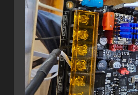
Already checked voltage polarity before wiring up? For my power supply I found white was Positive, so my white and black would have been swapped around what’s in your picture (thanks for sharing that). I would also add the pigtail/jumpers that Dan suggested.

Like Dan mentioned, the wire colors on these power supplies could be, but might not be… counter intuitive if you’re used to USA household electrical.

Would be good to assume everything is miswired until you’ve personally tested. I learned the hard way to ensure I measure everything, and power down before making changes.

image

You are correct the white is positive on this PSU, which is counter to what the standard is in the US. Glad having it backwards didn’t damage anything. I will now proceed to add power pigtail for the motors and verify how to get the steppes configured for 24v power.

Once you have your +24v attached to the power connector the right way around there is a jumper on the board labelled J2, with this jumper you can select whether to power your SKR from the incoming +24v OR from the USB connection.

1 Like

Thanks for posting the manual. The jumper looks like it is in the right place from the OP’s pic.

One thing to note: you can only power the logic from the USB. I’m not even sure it can power the TFT (if you’re using one).

It is useful when you’re flashing the board, but not in most other activities.

MB

I’m afraid your sentence ’ you can only power the logic from the USB’ can be misleading because you can power the logic from the +12v. I think you meant ‘it is only the logic that can be powered by the USB’ - which is true, but you can still select USB to power your logic whilst having +12/24v powering the motors, this way the logic does not go off if you switch the 12/24 v off, useful if you want to upload files to the SD card without powering the drivers and the motors, sometimes the computer and the CNC are not in the same room :slight_smile:

The TFT display is fed power from the VCC_5v so it will be powered from the USB if the selection jumper is set to short USB_5v to VCC_5v

Mike, thanks for rewording the statement. You’re right, although I didn’t know the TFT could be powered with the USB input.

Thanks for the correction.

MB