As you might know I use the LR4 mainly for ski building.
The typical workflow I use is:
cut out the core. I use a 6 mm endmill bit
glue the sidewalls to the cut out core
plane the core with sidewall to desired height. I use table planer for this.
core profiling
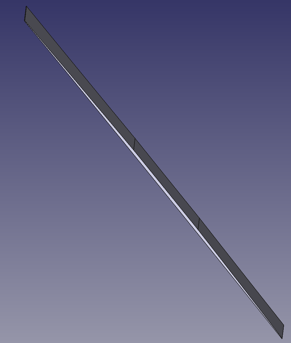
The core profiling is the tapering that goes from the center of the core to the tip and tail. I typically have a 40 cm region in the middle of the core at the maximum thickness (10 to 11 mm). the tapering then goes down to 2 mm to the tip and the tail. Right now to do this I use a hand planer mounted on a jig. I set the angle and I slide the planer until no material is removed anymore. With this method I have a straight tapering.
I would like to try with the LR4 for two reasons:
precision
possibility of doing convex/concave tapering
What bit should I use? The LR4 is my 1st CNC and I lack knowledge on this.
Here a few pictures of what the tapering looks like:
Since it needs to be moved in three directions, it‘s pretty hard to do and I‘d stick to the hand tool. It‘s hard enough to add a chamfer to a 2D object, because it has to be really, really precise.
Ultimately, you’re limited by bit geometry. Ye Olde Basic endmill will have a square profile, and getting a smooth taper might be… troublesome. Not impossible, as the machine can, theoretically, move the bit along the z-axis smoothly, but it probably won’t be pretty. A ball-end bit might mitigate a lot of that, as they are designed to sculpt rather than hog out material. But you’re still looking at at least one, if not two finish passes to get a decent result. And you’ll never get a crisp inside corner, as all bits are round (and even if they aren’t, the motor makes them go ‘round), so if those inside angles are critical, you’ll still have to tune them by hand.
Now, that being said, if you already have the jigs, you could use those in the LR, and have it basically flatten the ends of the core like you’re doing now by hand. Still probably want to do a very thin finish pass to get best results, but with the right jig(s), you could work on multiple cores at once.
Doubtful. Unless you have a spindle with good speed control, those bigger bits can be a bear to work with. Technically, we’re already outside of the working envelope of CNC endmills when we use trim routers. Those bigger bits need to be run in the 1000’s of RPM, and we’re usually in the 10,000’s of RPMs. I happen to have my Kobalt box next to me, and one of its selling points was that it could go down to 10,000 RPM. Flattening bits really should be run in the 3-4000 RPM range (if memory serves). You could probably run a big 1/2” bit with few problems, and I know some guys run flattening bits, but they’re usually skimming tiny amounts of material off of stock, and really cranking down their spindle speed. And it’s not just a cutting issue (you can’t just speed up the gantry motion to make up for the faster bit speed), it’s a momentum of the cutter head issue. When you have a Tormach and four tons of cast iron, you can fling a huge bit out on a long lever arm at insane speeds, but with our rigs, not so much. Ever tried moving a gyroscope?
Edit: I know it sounds like all gloom and doom, and people (me) telling you you can’t do all this cool and useful stuff, and really, I’m trying to relay the information I’ve gleaned here to help you avoid potential pitfalls and failures that could cause more frustrations. The reality is that you might get away with running a flattening bit just fine, if you happened to hit upon the right CAM for it. Or you could end up chewing through your stock, or worse (think of those little carbide inserts, how fast they’re moving, and where they will go should they lose their primary connection to the bit). With luck, a more experienced head will pop up, and give more meaningful help.
If you use a bit like that, you’ll end up with stairs.
I’ve seen some really cool 3D carving on a low rider. They all use a small ballnose bit so the machine can make any contour. But even a 10cm by 10cm block can take hours. I believe you can do it. It will just add a lot of hours and I doubt it would be worth it (but you’re the expert).
Alternatively, if you want to just replace the planer and replicate the straight cut off, you can use a surfacing bit like that. You need to mount the core at an angle so the bit will cut flat. I would still worry about tearout with a bit like that. You can get a much sharper blade and finer finish with a hand tool.
Is there a say to use the CNC to make a better jig for your planer? Maybe making a profile for the plane to glide along? If the front and back of a plane were on bearings and the bearings rode on a convex track, the tip of the plane would also follow a convex shape. It would be possible, but the exact configuration may need some more thought. Or maybe adjusting stoo blocks so your existing jig would adjust the angle down, while restricting the cut to smaller and smaller regions to simulate a convex curve, but in small steps.