Thanks guys. I thought it was different enough from the other stuff I saw in the gallery, so thought I would post.
TinyM was on the radar as a potential group buy in an Australian maker discord, but we ended up doing a massive group buy for Annex Engineering K3 
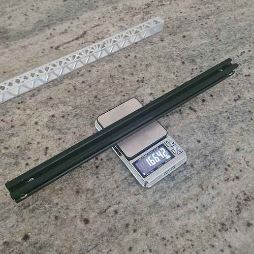
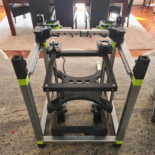
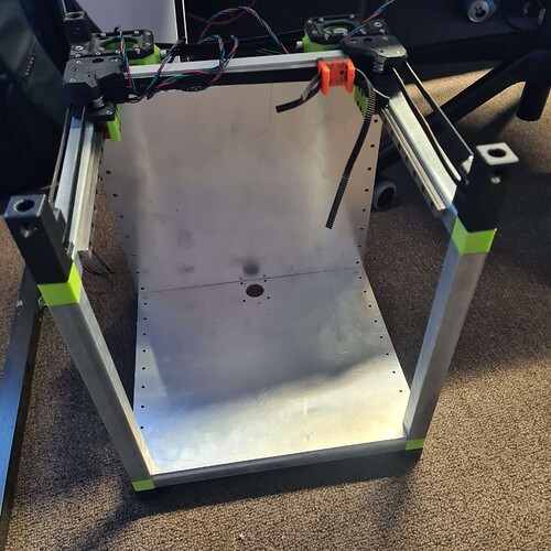
What I always wanted was a printer that wasn’t super specific about which extrusion you used, most stuff is very specific about the width of the channel in your extrusion, and despite infinite cheap options, people seem to end up buying stuff from misumi and importing it. So tiny M seems like it goes on anything. I made one with 20 dollars of steel from Bunnings and it really just goes on anything.
The same motion system bom as the tiny M I got a 180x180 vs a 120x120 build area.
The final push was when I put together a rook and looked at all the parts I was using and realised I could make something with with a much bigger build area with the same parts.
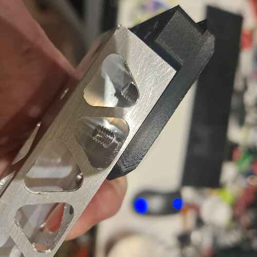
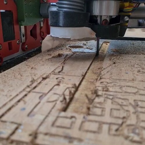
The plates are cut on lowrider too, but I was using some bottom of the barrel endmills, so not showing those cuts off. I keep redesigning the Z. The original design has extrusion that eats a lot into the Y area, so i had to get rid of it. The goal is to have the best footprint to build area, so that slows me down. As a bonus, it has an absolutely beautiful tensioning mechanism on the v5, where you pull the motor in with an M5 bolt and it saves a lot of mess elsewhere.
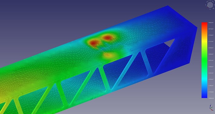
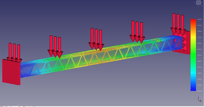
As far as FEA goes I watched joko engineering videos that in my mind validated freecad as giving solid results as solidworks, so have played with it on occasion, mostly to compare effects on steel thickness on rigidity fo PrintNC and other things. But just for fun. You can get into the flow of freecad if you are using it as the only cad, but it does get tedious. I was using it before I discovered onshape and now its hard to force myself to sit down with freecad. I spent a friday night trying to get results out of it and it was somewhat informative but frustrating. A week later, when I moved on to making my torsion table, i came across this thread.
https://forum.freecad.org/viewtopic.php?t=86698
The attached freecad files are stripped of results and some of the setup. It was incredibly rewarding to be able to replicate their posted results with the workflow from the previous week.
The interface sucks, but I understand all FEM is like that.
I checked out the wiki and the workflow picture kinda makes a lot of sense, but admittedly after I banged my head against my desk a fair amount.

You get your part, constrain it, load it, mesh it and then solve it. The sub menus for viewing results and specifying which load you are calculating are a little confusing. But once I know where they are I can get the ones (I think ) I want. Also I have a couple of engineer friends in the maker discord, who I show these coloured pictures to. And they usually inform my next step or the reading tangent i descent into.
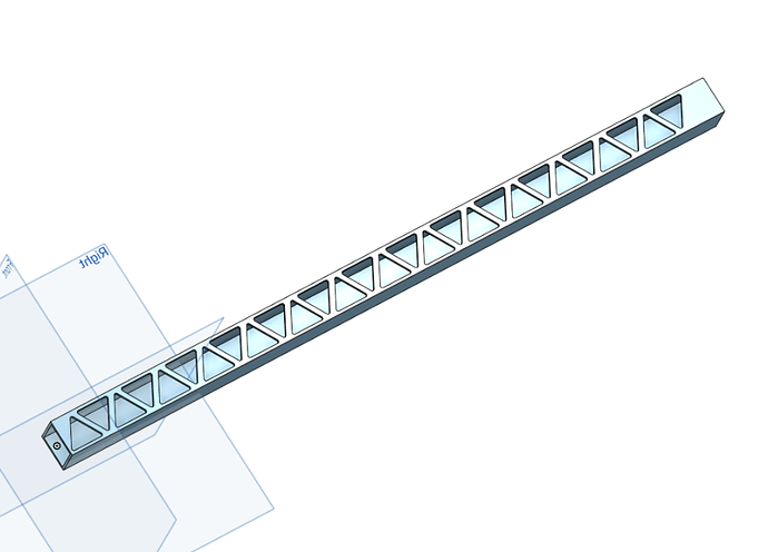
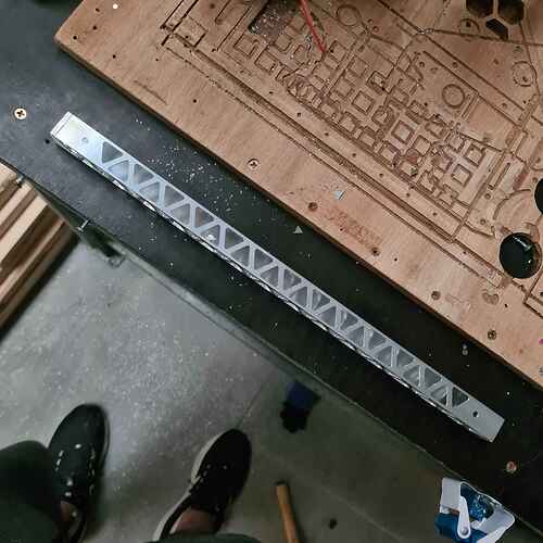
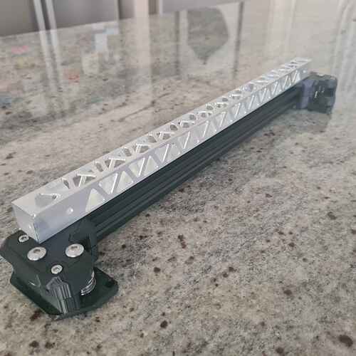
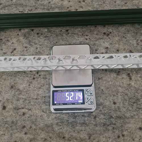
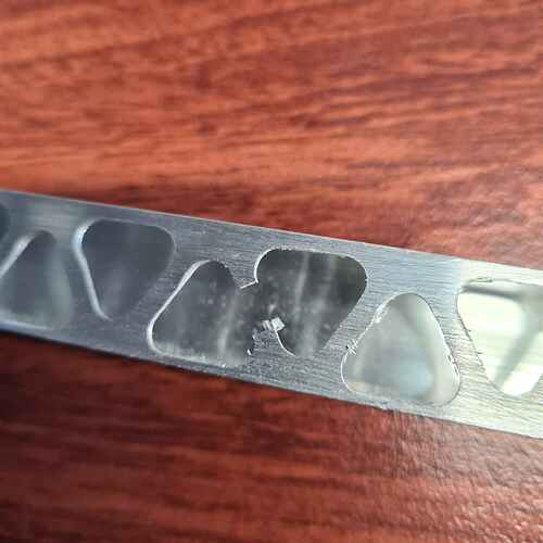
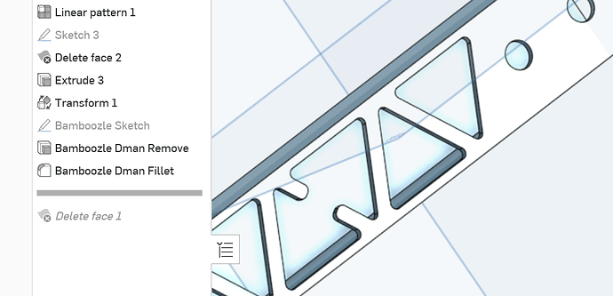
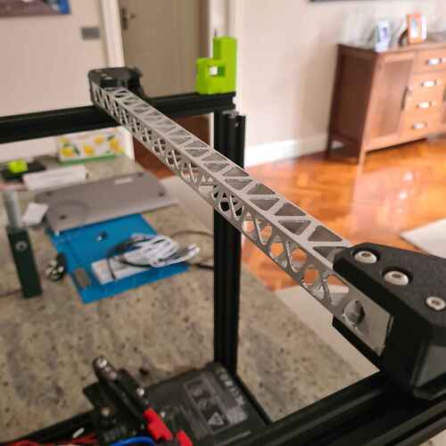
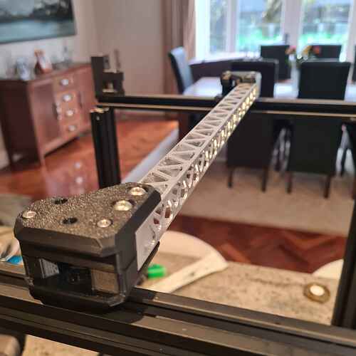
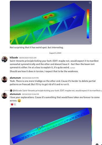
The triangle pattern is imperfect too. In first image there is one extra one, in the second one the extra is removed, but the spacing is uneven. The two base triangles are spaced with a 2mm distance between the parallel edges, but when I pattern it, I am eyeballing the distance rather than doing the math to get them right. I am hoping to figure out a workflow that allows me to mesh parts from onshape and do FEA on them, because it’s just such a sanity saver. But if I want to progressively test some parametrized designs.
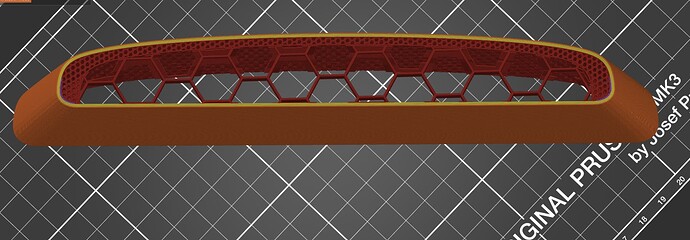
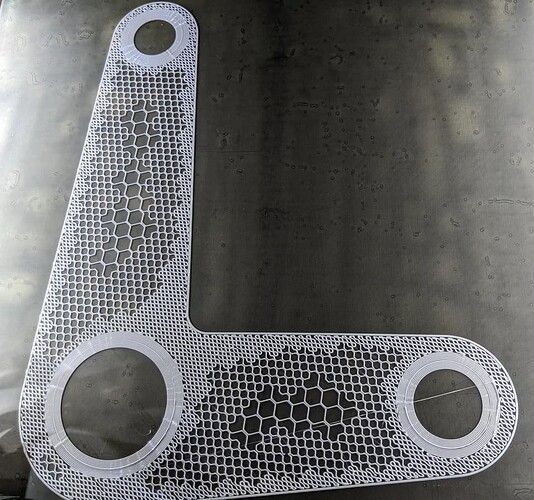
I actually remembered my first play was an attempt to make variable infill based on stresses, where you break down the tiers of stresses and export them as geo and use that geo as a modifier in the slicer to increase infill %. You will have to use your imagination but here is a surfboard with an internal modifier for sparse infill while the outside is denser.
And here is a commercial result that does the same thing.
I think the core on lowrider might benefit from something like this, or even printed ZX plates, Definitely the braces… But I think the setup would be out of my reach for the time being. Though there is a potential to save people some printing time or get more strong for your buck.
