Simple squareness checker for MPCNC's

Warning: This is NOT rocket science. If you don’t need this tool, you just don’t need it.


Functional squareness is pretty much requirement for any of the various versions of the MPCNC–Burley, Primo, LR2, LR3, etc. When you rout a circle, you want it to be a circle, not an ellipse.

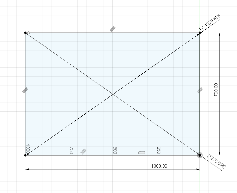
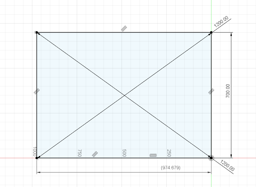
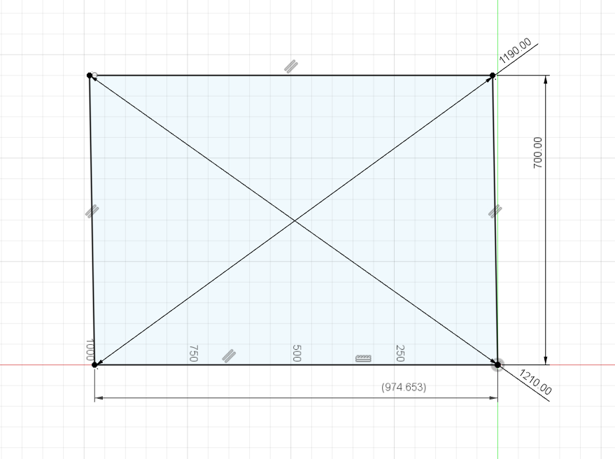
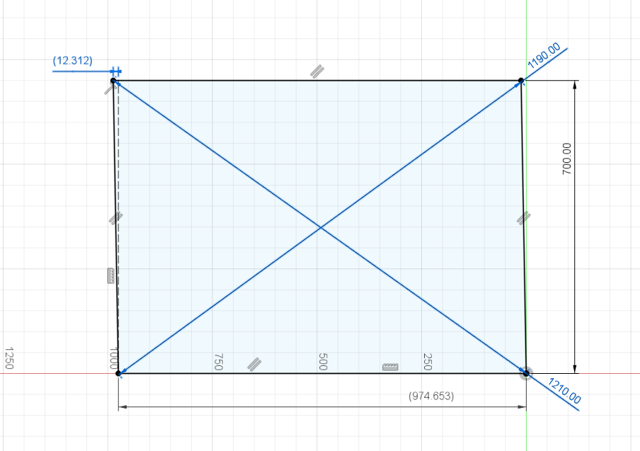
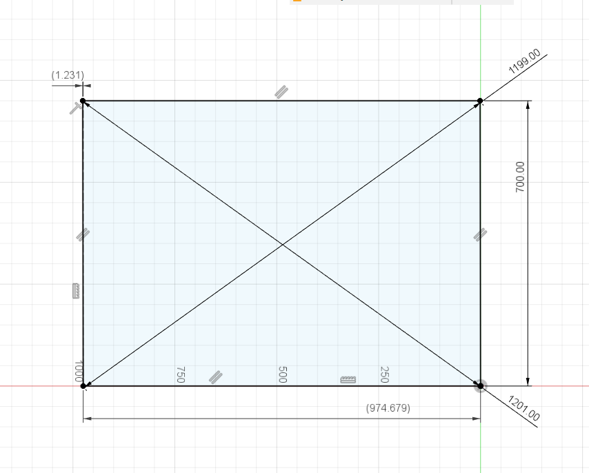
One of the key elements to confirming that your CNC router is operating correctly is the measurement of the diagonals of rectangular patterns. If the machining is square, the diagonals will be identical. For those using dual endstops on x or y, the usual method is to draw something and measure the diagonals, followed by a correction and repeating the process.

For large tables, I have found this difficult to do using a tape measure when I don’t have a helper. While there are various ways to do it, I wanted something that is quick, easy, adjustable and accurate. To that end, I found a yardstick-based trammel point design on Printables ( Printables ), and did a simple re-mix so that the pivots now have a pointer that has a spherical shape, 1/8" in my case.

By using a 1/8" ball nose router bit, and routing shallow dimples at the corners of what is supposed to be a rectangle, you can check the diagonals by yourself since the tip of the pivot forms a sort of kinematic connection to the routed dimple. And, since the beam can be a simple wooden yard stick, the fabrication is very low cost. Or, if you need a longer beam, it’s simple to fabricate. Of course, you could still use a nail and mark the corners with a smaller probe or with a pen. But, with no assistance, I don’t find those methods as accurate.

Some pics may help.

Overview of Story Trammel (ignore the clutter)

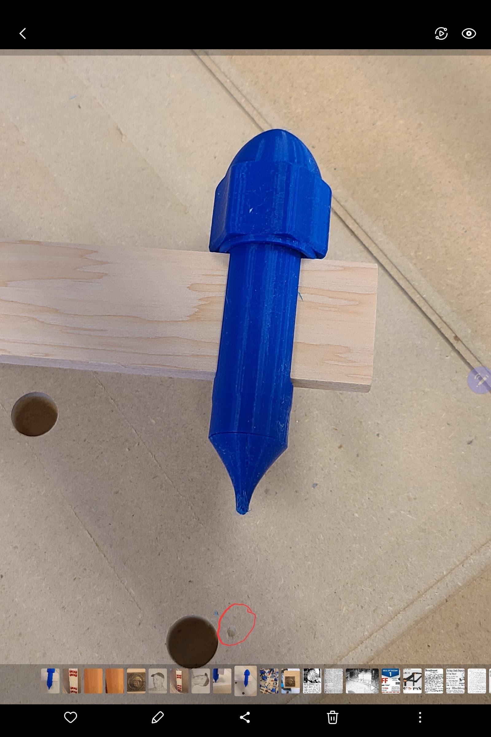
Shows the pivot and the dimple (circled). This was about 1mm deep.

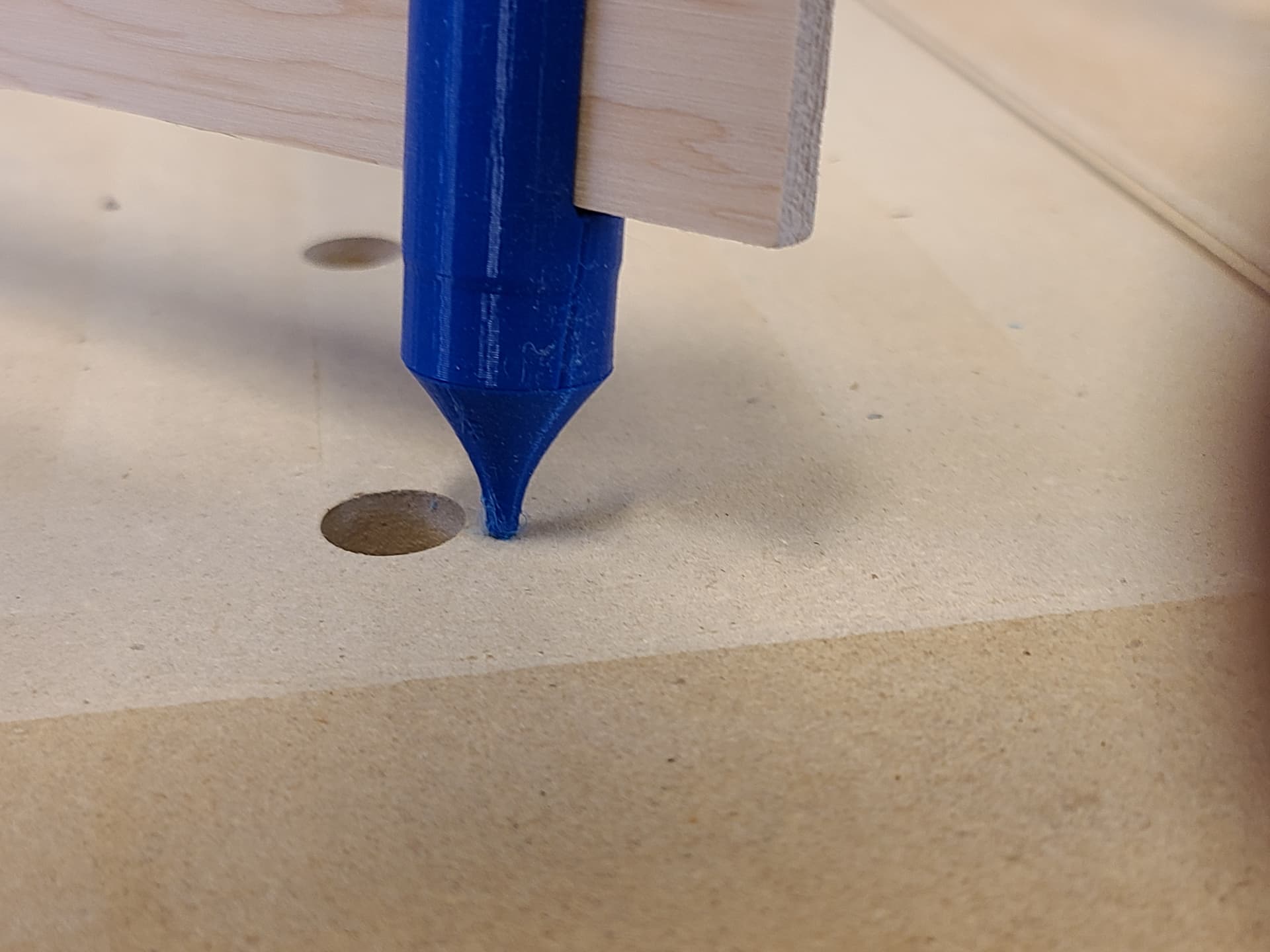
The pivot point placed into the dimple. There is no detectable “slop”, which suggests the accuracy must be better than 0.1mm. Maybe a lot better.

I actually got lucky and after only 1 adjustment of the dual endstop, had a perfect fit on both diagonals. I think #Primo.new is ready to go…

Here’s a link to my remixed pivot ends.

https://www.printables.com/model/880548-story-stick-version-of-yardstick-trammel

10 Likes

So nice! I’ve needed this every time I’ve built a new CNC machine.Thanks for thinking of it and making it available.

Now, I need to go turn on the 3D printer and start the flow of plastic.

Mike

Yep. And, the nice thing about this particular approach is that you can disassemble it and store it until you need it again. Or, you can use it around the shop for other “story stick” types of measurements.

I actually tried to size connections to the tips (for the 1/8" dowels) so that they are only press fit onto the main pivot assembly which also means that you can change the size or shape as you need to for various purposes.

If you want to simplify the process even further, you can make the diagonal a known and round number by carefully choosing the sides length
Then your tramel can be a fixed length (eg. cut from factory) and if one diagonal is the right size the other one should follow

For the sake of completeness…

I use this F360 sketch (the same can be done with onshape) taking special care of the constraints

I first constrain the width and length to get me in the ballpark of my work area size

Then I can toggle the Y size to “driven”, and the diagonals to “driving”, and adjust the diagonals length to a round number so that I get the adequat Y liength for my squaring marks

eg: I need X=700cm and Y=974.679cm to get a 1200cm diagonal

Once I have these inputs, I generate my squareness check marks gcode using @jamiek 's generator
I can run the program, check and measure the diagonals, and enter the diagonals size in the sketch

I can finally add a construction sketch line and constrained dimension (top left) so that I can vizualize how the axises are skewed, and by how much

Then it’s just a matter of adjusting one Y endstop by 1/2 the indicated number, rinse and repeat until it’s square-ish

The sketch really helps visualizing the skew and taking the guesswork out…

I think there’s an even better/more precise way to do this using you trammel idea and registering the router bit itself, maybe I’ll give this a go some day…

2 Likes

I’d forgotten about the gcode generator. That’s a nice way to mark the surface, whether with a pen or the router.

But, the point of this effort is that for large machines (like a 4’x8" LR3) it’s not easy to measure the diagonals accurately. This device assists that process since it “locks into” the small dimple on one end. We don’t really care WHAT the diagonal length is… just that they are both the same.

Even on my Primo, which has about a 600mm x 600mm work area, if you use something close to that for the squareness test, the diagonals are about 850mm. Personally, I can’t see both ends at the same time to check the measurement.

Even with a helper, the measurement is only accurate to about half the smallest division of your measuring device… maybe 0.5mm at each end? Theoretically at least, if the dimple and the ball end of the trammel are pretty well matched, the accuracy of the placement can be MUCH better, likely better than 0.1mm.

(As a matter of interest, I was thinking about the technique shown in this video, but didn’t have a spare set of calipers and length of aluminum angle handy.
https://youtu.be/WDCZW4tIDl0?si=QpBTWJ1YELGLSt7p )

Is that kind of accuracy needed? It depends on what you are doing, of course.

1 Like

This is where I think both techniques can be combined
You can buy a piece of stock (wooden tassle, dowel, tubing, …) that is of known length, and then use the tip I gave to match this length on you diagonals
Then it’s just a matter of measuring the gap between your reference “stick” and the actual mark to get an estimation of the correction needed