Scara sand table - Arduino

Actually, I want to make a sand drawing table. (as below in image 1) using the below mechanism. (as image 2)(images are getting from the internet)

image

image1018×631 72.8 KB

image 1

image 1246×205 8.71 KB

I don’t have good knowledge about robotics. Now I bought Arduino Uno, CNCShield + A4988, and two Stepper Motors NEMA 17. Now I want to know

  1. What is the firmware or code that I want to upload to my Arduino Uno?

  2. What is the software I use to make designs (if that is https://sandify.org/ waht is the export type(.scara or .thr, or .gcode, or other)?

  3. What is the suitable software to send a G-code file or any file to the robot?

  4. What is the software or Python code to if want to convert one type to another type?

1 Like

hi Jeffeb3

I created a new public post.

  1. Can you send me the correct GitHub link for Grbl that you mentioned?

  2. And I want to know below export is correct for my function?

hello Jeffeb3

i am waiting for your help………

The link Tom sent seems fine. I am not as familiar with it as Tom. So I would trust him.

The documentation for the export is here. Those settings look fine.

Tom Traband & Jeffeb3,

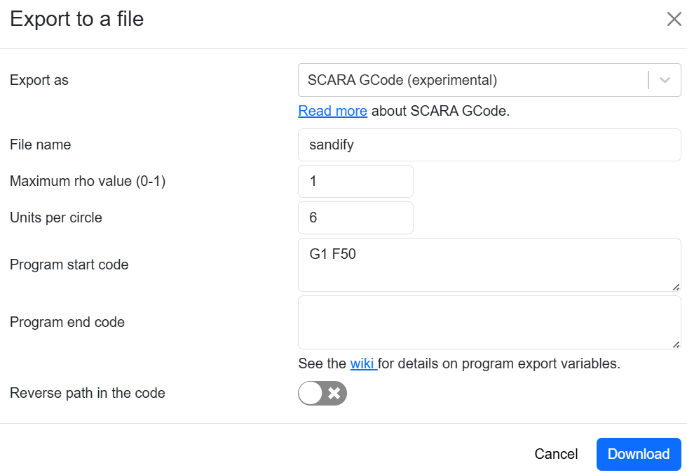
I followed the instructions you gave exactly. But I still couldn’t control the robot properly when I was given a design. If you can, please provide me with a G-code that you know.

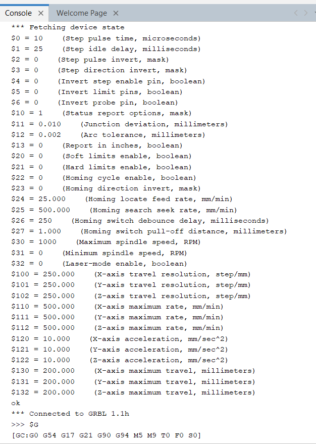
to check whether the GRBL parameters I am using are correct or not, I will add that to this message as well.

$0=10 (Step pulse time, microseconds)
$1=25 (Step idle delay, milliseconds)
$2=0 (Step pulse invert, mask)
$3=0 (Step direction invert, mask)
$4=0 (Invert step enable pin, boolean)
$5=0 (Invert limit pins, boolean)
$6=0 (Invert probe pin, boolean)
$10=1 (Status report options, mask)
$11=0.010 (Junction deviation, millimeters)
$12=0.002 (Arc tolerance, millimeters)
$13=0 (Report in inches, boolean)
$20=0 (Soft limits enable, boolean)
$21=0 (Hard limits enable, boolean)
$22=0 (Homing cycle enable, boolean)
$23=0 (Homing direction invert, mask)
$24=25.000 (Homing locate feed rate, mm/min)
$25=500.000 (Homing search seek rate, mm/min)
$26=250 (Homing switch debounce delay, milliseconds)
$27=1.000 (Homing switch pull-off distance, millimeters)
$30=1000 (Maximum spindle speed, RPM)
$31=0 (Minimum spindle speed, RPM)
$32=0 (Laser-mode enable, boolean)
$100=800.000 (X-axis travel resolution, step/mm)
$101=800.000 (Y-axis travel resolution, step/mm)
$102=250.000 (Z-axis travel resolution, step/mm)
$110=100.000 (X-axis maximum rate, mm/min)
$111=100.000 (Y-axis maximum rate, mm/min)
$112=500.000 (Z-axis maximum rate, mm/min)
$120=10.000 (X-axis acceleration, mm/sec^2)
$121=10.000 (Y-axis acceleration, mm/sec^2)
$122=10.000 (Z-axis acceleration, mm/sec^2)
$130=200.000 (X-axis maximum travel, millimeters)
$131=200.000 (Y-axis maximum travel, millimeters)
$132=200.000 (Z-axis maximum travel, millimeters)
ok

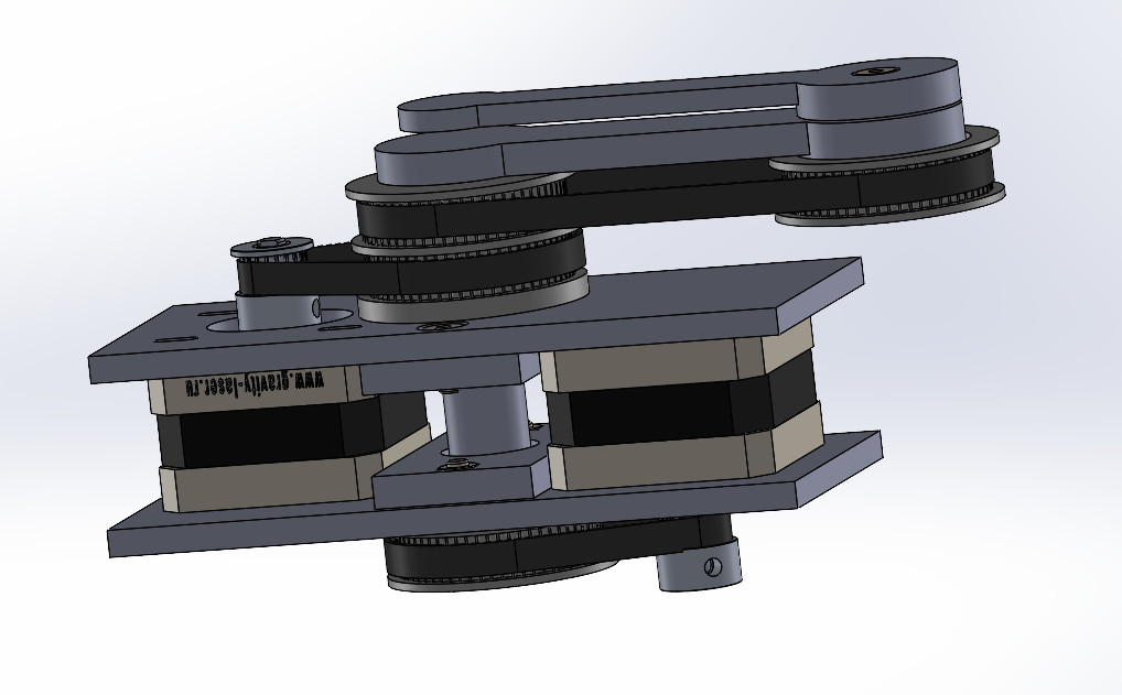
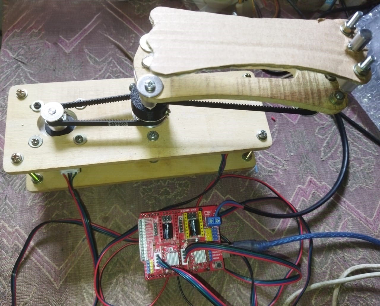
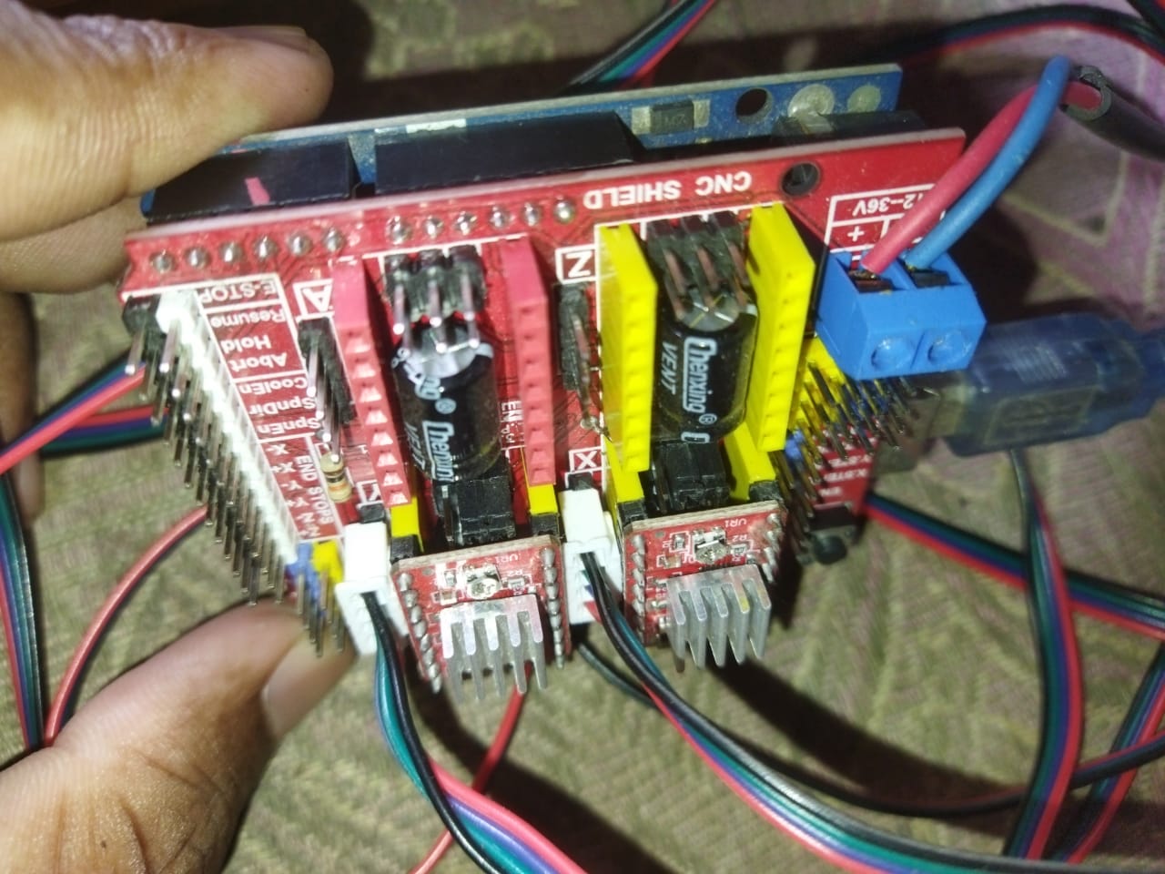
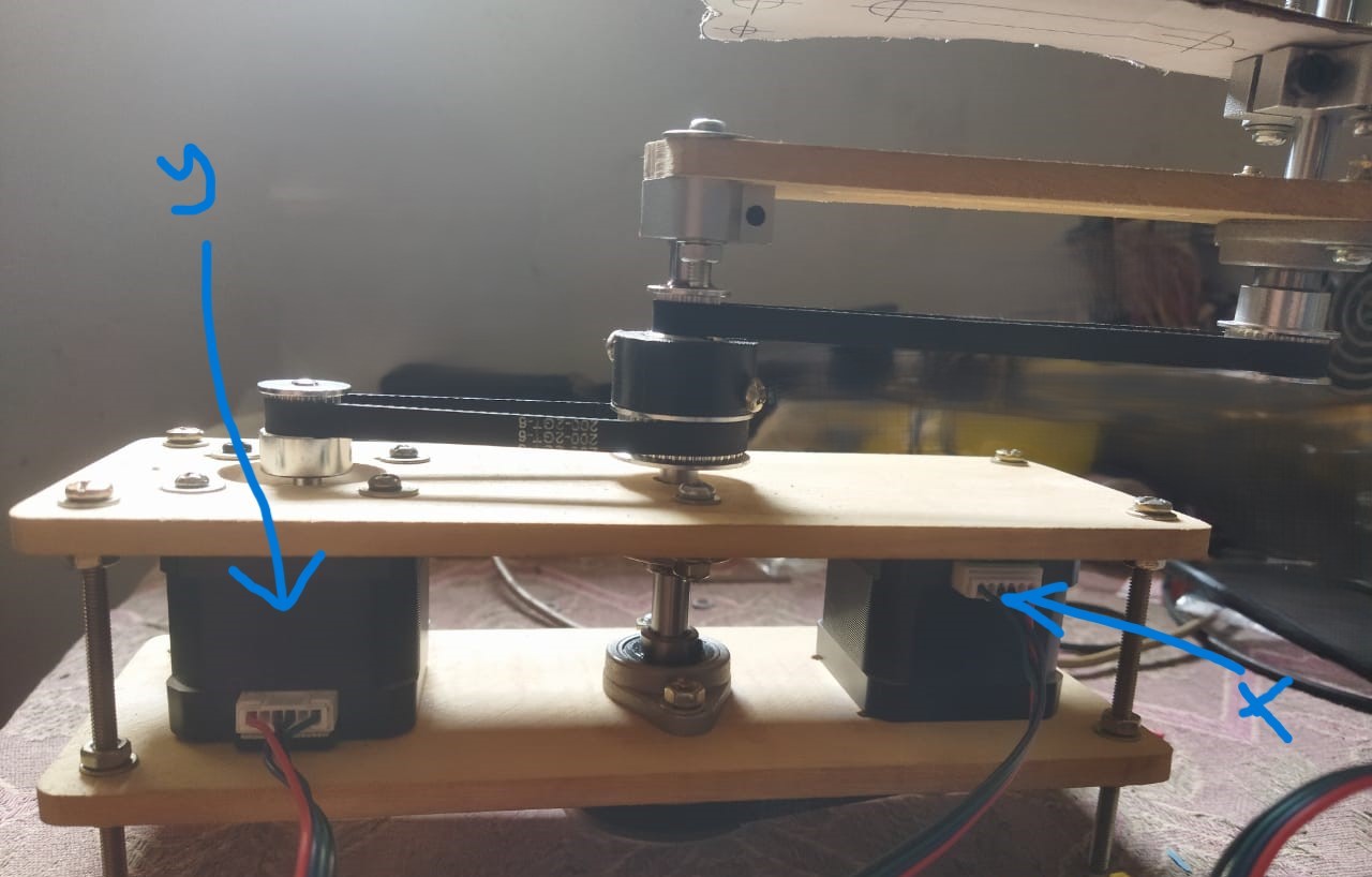
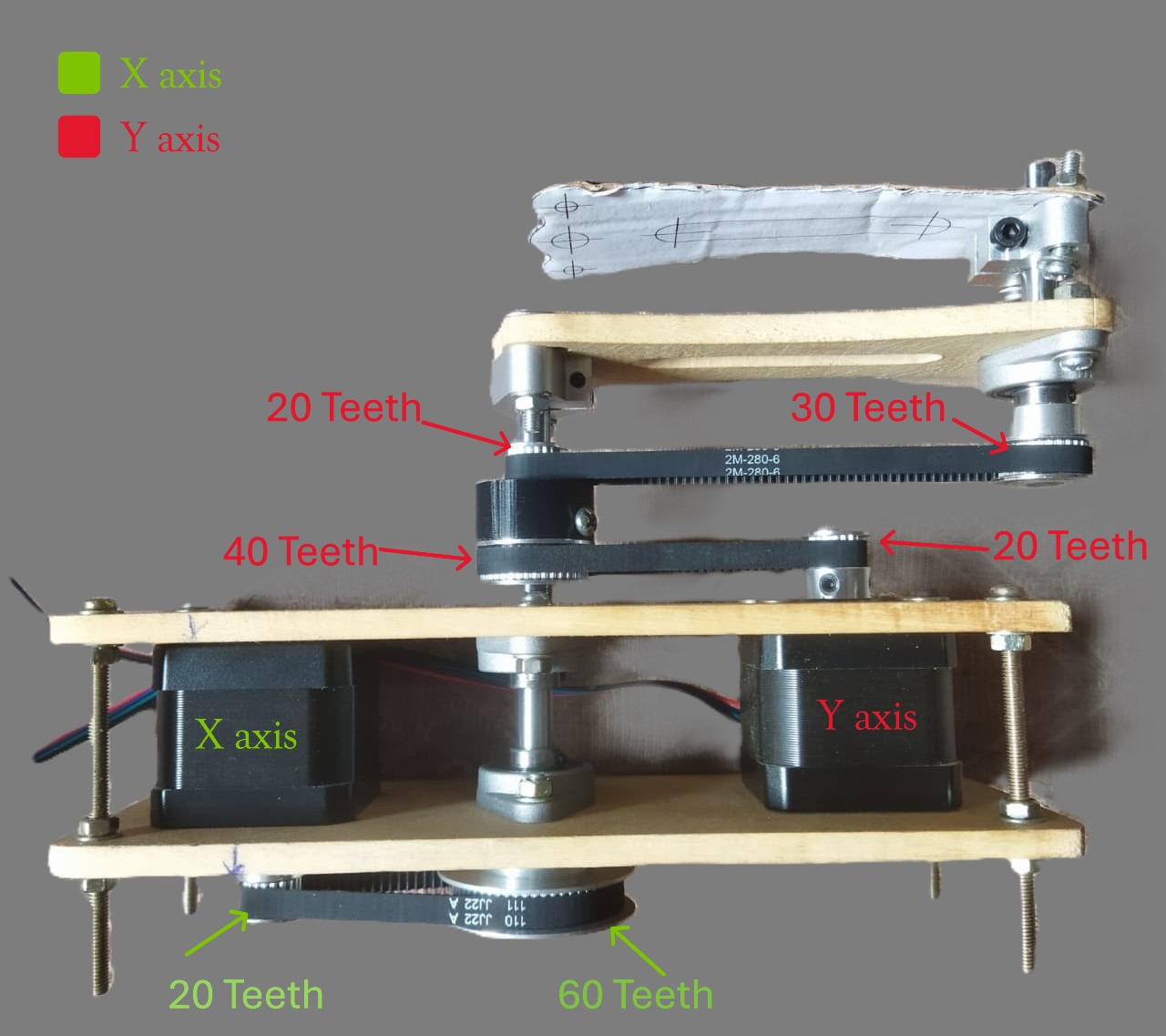
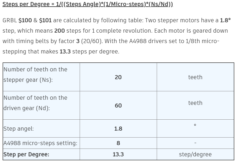
and images of the robot (arm length=115mm, cnc shield microstep resolution = 1/8, Gear ratio of both axis 1:3)

Where did you get these numbers? Have you tried manually commanding one rotation with G1 X6? I’m guessing that may be problem #1.

You also need to zero it before you start. Do you have a method for doing that?

First, I uploaded the Releases · gnea/grbl into the Arduino board. And after that, I go to Universal G-code sender. It shows parameters as below in the console…

I change it according to my knowledge. I don’t know, it is correct or wrong. What should I do now?

when I give G1 F50 x6 to robot using UGS console, 1st arm rotated 1 round but not 2nd arm any move.
when I give G1 F50 y6 to robot using UGS console, 2 nd arm rotated 1 round but not 1st arm any move.

That should be right. Once around (should be very close to exactly one revolution). The math on the sandify wiki comes up with something closer to 533 steps/unit, not 800. But your ratios are different.

Start with a pattern from sandify that is something simple, like a circle or a square.

hello Jeffeb3,

I’m happy to say that I tried this on Christmas Day, and I solved that problem. The problem was that I had set the robot’s y-axis motor to move in the wrong direction and set the wrong value in $101 (Y-axis travel resolution, step/mm).

Now, I need to confirm and set the value of $101 (X-axis travel resolution, step/mm) & $100 (Y-axis travel resolution, step/mm) of the two motors on the X, Y axes of the robot. I need your help for that.

I designed the X-axis (shoulder arm) of my robot as follows,

Motor=Nema 17
X-axis microstep size in CNC Shield =1/8
gear ratio= 20:60 (1:3)

I designed the Y-axis (elbow arm) of my robot as follows,

Motor=Nema 17
Y-axis microstep size in CNC Shield =1/8
gear ratio= 20:40 (1:2) and 20:30 (1:1.5) (overall 1:3)

It’s Christmas, you posted one day ago, have a little patience. I am sure Jeff is going to help you, but nagging won’t help. :sweat_smile:

2 Likes

I’ve never run a SCARA bot or sandify. My ability to assist was limited to elements of the CNC shield and grbl versions.

Very basic question (which may show my ignorance of SCARA) are you sure the motors for the shoulder arm and elbow arm are properly connected? If they were swapped, would that maybe explain the unusual movement in the video?

Jeffeb3

Reading over this thread, I’m not sure what you even need help with.

I didn’t see where you answered this.

Did you ever try this? What was the result?

What are they currently set to? What is the current behavior? What have you tried? I don’t know much about SCARA but I think you are trying to set it to steps per degree? or maybe steps per radian?

Looking here, it seems that maybe you need a value of 13.3? I may be completely off base here.

D.I.Y SINGLE ARM SCARA ROBOT : 8 Steps (with Pictures) - Instructables

I won’t be able to help much here. I’m in planning stages of creating a scara bot, but my plan is to use a coaxial stepper and an unreleased FluidNC build where it will use cartesian coordinates in gcode and FluidNC will handle the translation.

This is how I work it out:

200 steps / shaft revolution * 8 microsteps / step * 1 shaft revolution / 20 teeth * 60 teeth / arm shaft rotation * 1 arm shaft rotation / 6 “units” = 800 microsteps / 1 “unit”.

So 800 looks right to me. I computed 533 for my imaginary machine, but that assumes 1/16 microsteps and not using a 3:1 ratio.

I don’t see a reason your X and Y should be different.

Does the X axis affect the Y shaft? It seems like it would if that gear if firmly attached to the X shaft.

1 Like

Jeffeb3,

The Y-axis (elbow arm) of my robot has a gear ratio of 20:40 (1:2) and 20:30 (1:1.5). So, should I also do the following thing also my robot? (My robot still has a drawing problem with some designs)

That should all be handled by the steps per unit config value and it should be the same as the X.

1 Like

If you want the best chance of my help to be useful, you’ll need to read the entirety of the messages I’ve sent and answer the questions I ask. I’m not asking them for my benefit.

3 Likes