In another thread @azab2c asked a couple of questions which I promised to answer. Sadly it’s taken a bit longer to think up an answer than is reasonbable, but here goes anyway.
“Workflow” is probably indefinable, as this process is quite dynamic for me. Something fundamental to the design, like perhaps check fitting a thread to a vacuum hose would happen very early in the project.
In that case I’d usually do a very thin slice through the thread to make sure I had the pitch and profile close to correct, and when satisfied that works, I’ll do a small (perhaps a centimeter (half inch) at most, cross section to check it screws on.
With parts like that I tend to build the fit as the document proceeds so that at the end of the drawing I have something that will just work from the first full print.
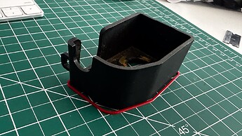
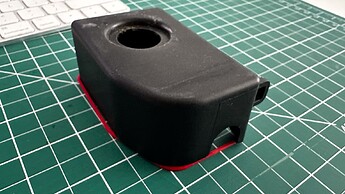
Here’s something that should be simple but because of warping on the case turned out not to be - it’s a battery terminal cover for my van - the black part is the base and I’m making a lid to fit over it.
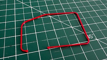
The “slice” for this one is only a millimetre - you just need enough plastic to be sure that the trial part will hold it’s shape. You can easily see that my measurements were spot-on, but because of the warping the finished part as designed won’t fit the other end - but it’s now easy to photograph and adjust the drawing accordingly.
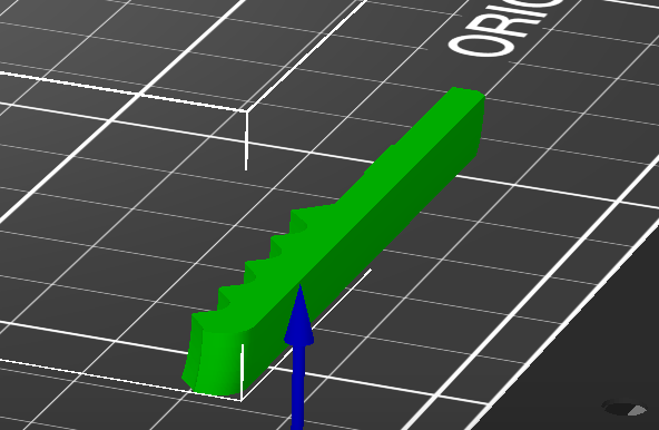
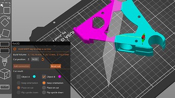
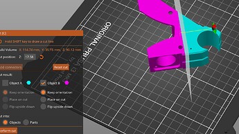
Slices can be as complicated as you like. (with Prusa Slicer)
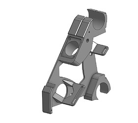
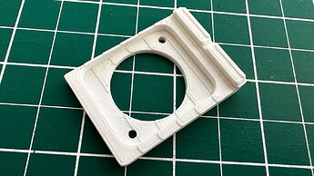
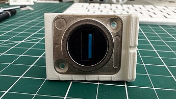
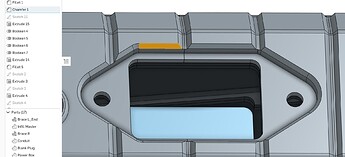
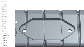
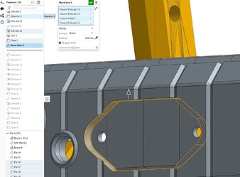
Today’s task was to check that the pass-through USB plug fitting will fit as it’s supposed to, into this rather complex part for the LR3. I’m going to slightly modify the board mount brackets and will check them the same way before printing the finished part.
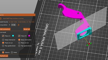
Prusa Slicer makes it super easy to take as many cuts as you like to excise just the bit you need. There’s no need to muck around modifying your CAD drawing.
The end result is a quick and dirty print of just the part you want to check.
Despite the perspective, the screw holes are perfectly aligned, the depth of recess spot on, and the part is a press fit, which I will modify slightly to make sure it still fits when printed in the intended orientation.
The second or perhaps first part of the question I think related to CAD workflow for this. I don’t know how other applications work, but Onshape has a few different ways to sort out things that might have been caused by changes.
Things to explore if you can -
- the “roll back” bar, which let’s you go back to any point and insert other operations or make small corrections if you broke something at that point.
- Creating a “fork” - literally. If you want to go back to a place in time, you can “fork” a parallel design from where you wish, leaving the original intact. I’m not good at that, but it’s a great way to track back if you break something on the way through.
Hope that helps someone!
