Haha. I still don’t get it. I have a model based on the description, but the banana makes no sense. I would expect to see more like sunglasses centered in the middle.
The M1 motor moving on it’s own should move the elbow, but the angle from the elbow to the magnet does not move, right?
You don’t have to make me understand, FWIW. But I am curious. Would it be possible to take a video? Maybe without the sand on top?
Re: “The M1 motor moving on it’s own should move the elbow, but the angle from the elbow to the magnet does not move, right?” - no, it does (and I think that’s the key).
For demonstration, I did …
“G92 X0 Y0”
“G1 X2 F40” ; 8.28 represents 1 full turn
See video link - https://youtu.be/StVKZH_Da3Q
If M1/shoulder(X) moves and M2 (Y) doesn’t, M2 and the “M2 gears on the M1 shaft” hold steady.
That forces the gear at the elbow to turn the lower arm to stay in sync with the upper arm.
Maybe the contraption I created is bananas!!
Oh! I see. Interesting. “A video is worth 1000 pictures (at 30Hz, for 33.3s).”
So, we need to update these equations.
So if we were trying to flip the arm completely around to the other side (traveling on the outside), we would want a theta of pi, and an alpha of zero.
G1 X4.14 Y-4.14 F40
If we wanted to move it to the center from there (along a straight line):
G1 X2.07 Y2.07
Then to move it back out, but at the bottom would be:
Yes, the scale (UNITS_PER_ROTATION) is set to 8.28.
M1/X movement needs to be factored into M2/Y.
I was imagining the need to adjust Y like this: 'Y = Y - deltaX
Let me review your equations though & then give them a go.
Thanks for all your help!!
This may not be the right place to ask this question, and if it isn’t just let me know and I’ll start another thread…
How do you guys mess around with the motor equations in the firmware? I have looked around in marlin and it wasn’t obvious to me where to start playing with this stuff. I did some research here and there on a night or two of rabbit holing because I love the idea of a polar table for some reason, but just never really got anywhere with it.
Yes, we have no bananas.
The updated equations which compensate for M2 movement when M1 moves, make sense: -1 * theta - 3 * alpha
And now it’s working.
Thanks Jeff!!
Oh and VERY IMPORTANT.
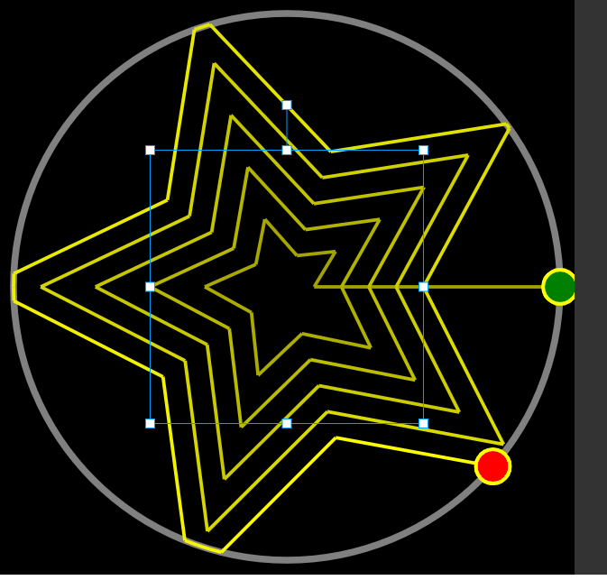
The pattern must start on the perimeter (green dot).
I fully extend the arms to the perimeter + label with “G92 X0 Y0”
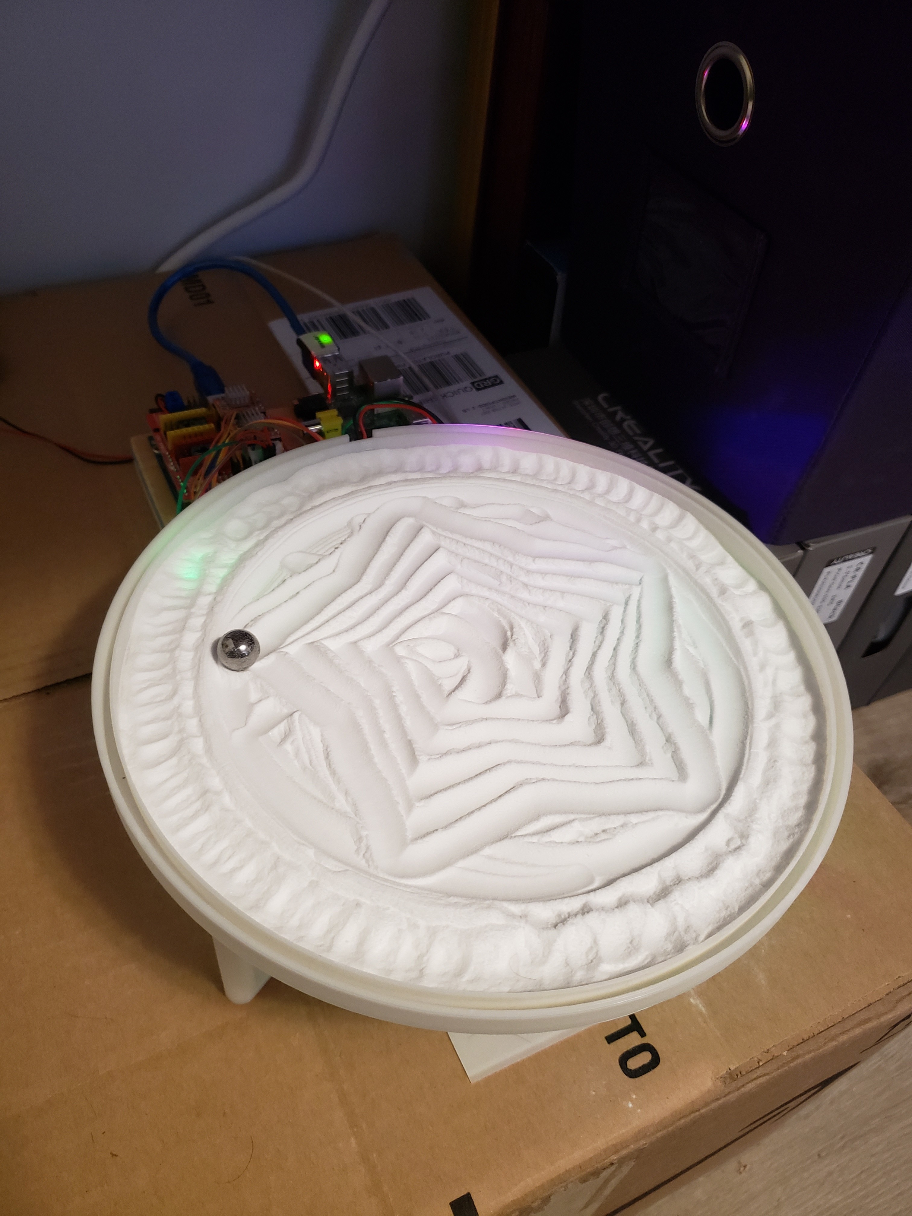
I'm been trying different patterns from sandify.
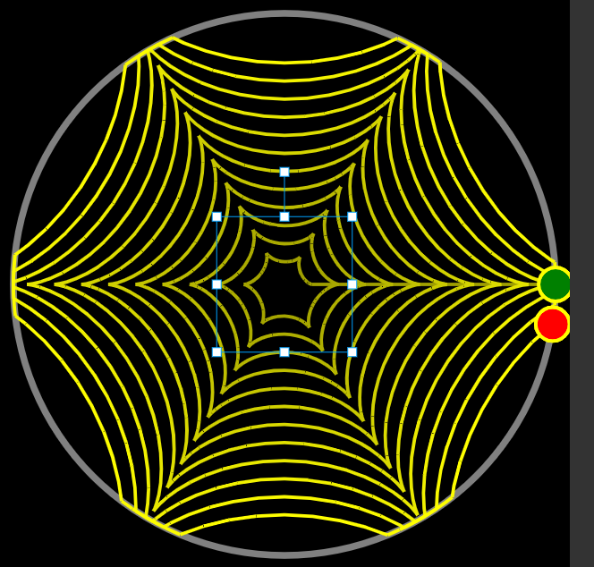
The web pattern resulted in a .thr with a rho=1.00001 - see below
And the python math acos(float(rho)) threw an "math" error.
I included a if (float(rho)>1.0): rho="1.0" line to workaround it.
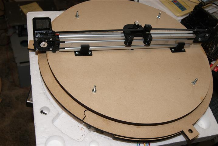
I have a problem. The Ro is a 120 tooth mdf gear mounted on a large lazy susan quiet bearing and driven with an 18 tooth pinion. I am using a arduino uno with a cnc shield. G code is sent by the Universal G code Sender (UGS). The problem is that the theda axis doesn’t respond properly . It like the acceleration and maximum speed is set wrong however, I have spent hours changing the ini file to get it to work properly. I suspect that the problem is either the Uno or the UGS. I have eliminated any mechanical problems or stepper problems because I can set up and run both axis using my cnc G code interpreter called Mach3 and I used a Gecko G540 for the drivers. Is The UNO inadequate to run a polar table? Any suggestions and recommendations for a better controller?
Is the theta accurate? If you send it a half circle, does it eventually get there?
The theta is tricky because, really, there should be a limit on the rate of angle change (which is easy) and a separate limit on ball speed (which requires some more math in the firmware). The first will have a bigger impact when rho is small and the second will have a bigger effect when rho is 1.0.
I am confused by your reply but think my post caused the confusion. The problem is with the Theda not Ro. I switched the theda and ro when I posted. Again the problem is that the theda stepper doesn’t rotate correctly. As I mentioned I used an different driver and a difference CNC program to confirm that the theda stepper and axis rotates correctly. So I have eliminated the stepper and mechanism as the problem. So is the arduino uno adequate with enough bandwidth to adjust the acceleration and speed? Also is using the Universal G code Sender adequate to set the parameters for the ro and theda?
I can command the theda to rotate to the desired angle using mach3 software and a different driver.
Maybe explain in detail what the issue is (and maybe open a new thread). I was trying to help with theta, not rho. But it would help if I knew what the actual symptoms were.
I found that the problem was with the arduino uno. So i have employed a mega 2560 with a ramps 1.4 and discount display. I can tell that it runs the axis much better but not for a piolar. . Can anyone give
me a link to software that will work with the mega and run polar axis.? I’m 79 so be patient with me.
Mine was a rectangular 120/55 cm similar to the Zen table on Kickstarter, but they wanted 10k$ For the table
Mech: nema 17, toothed belts, Igus N series rails
The built height as low as possible, 9 cm (otherwise it would not fit underneath the table
I used a Tonelli Fratina Due glass table for presentation
The difference is that with this set up you can present pictures, logos etc, as the ball is moved out of sight via the vertical “erase tracks” so there are no “connection lines”
Saw also some questions on which “sand” to use- I asked one of the guys of the Kickstarter project which had left- it was shuffle board powder- bit expensive, and can lump in damp conditions and left unused for a while- but forms clean tracks
Like your mini version of the sandtable.
As it looks like I have all the parts in house, was wondering if you are willing to share the files (fusion/stl) so I can build one.


 in sandify, and I’ll fix it.