my question is not about an MPCNC (which I have at home) but about a TTC450, which is the CNC we just bought for work (a school). I am in charge of the school’s makerspace, where we have many 3D-Printers but also a CO2 laser cutter and now a cheap China CNC (which is just for testing, hopefully we’ll get a proper CNC in the future).
I just assembled the CNC and I am testing it but I also need to come up with a safety concept for it.
Yes, students will get a introductory workshop and we’ll tell them how to work on the machine safely, they will also sign an agreement that they are not goint to touch any rotating parts, but I think it would be good to have an enclosure with a door switch that stops the spindle once the door is opened.
I was hoping that the safety switch on the TTC would trigger a pin that pauses the machine but in fact it disconnects the board from the power supply, so the machine is completely dead (which does make sense tbh).
But now I cannot use the safety switch (with a door switch in line) as every time the door got opened, the machine would restart, so, for example, opening the door to take out the z-probe would reset the z-offset just probed. That would not work.
Do you guys have any other idea how I could make sure that the machine does not start?
I thought about adding a switch between the board and the spindle, so power is disconnected from the spindle once the door is opened. But that would not stop the steppers from moving and could result in machine damage.
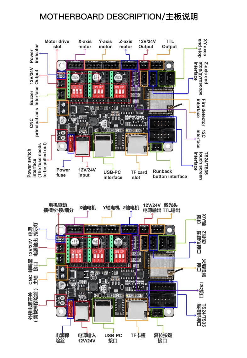
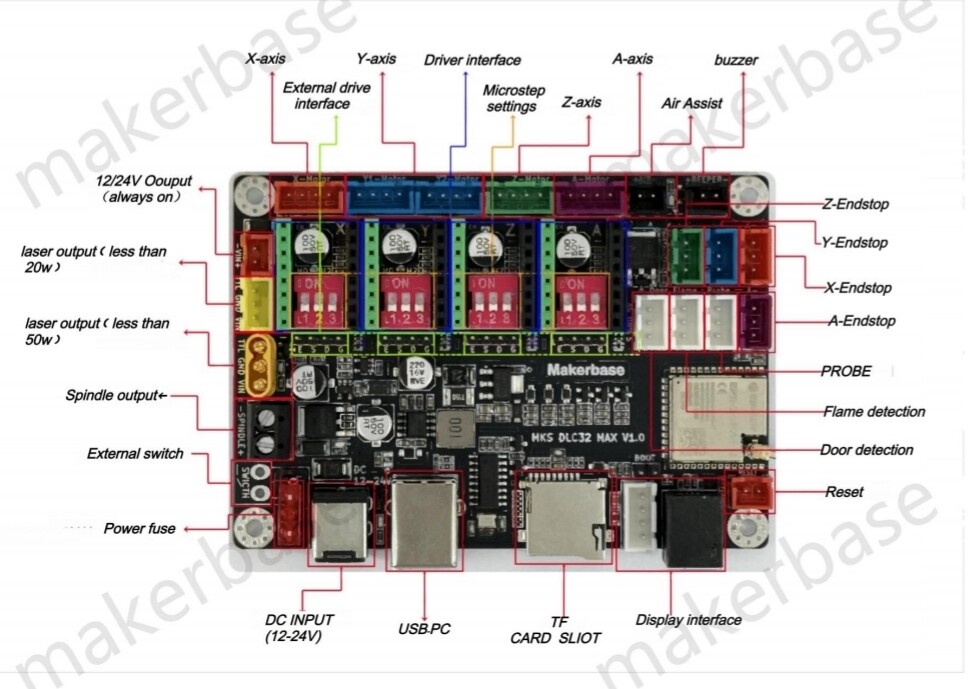
The machine uses a MKS-DLC32 as its board:
There apparently is a fire detector interface on that board and also a 12C interface, which maybe could be used?
I hope that it is okay that I am asking a non-MPCNC-related question here but I tbh did not know where else to ask.
Thanks!
The fire sensor will ONLY work with one particular revision of the LASER firmware. V2.0.8_H35_20220105_N.bin if I remember correctly.
There are no spare input pins left to use on the DLC32 to configure as a door safety switch and as the only firmware available for this board is the official pre-compiled MKS bin file you cannot edit the GRBL config to enable the feed hold function. I can’t see a way to do what you want apart from losing your program by cutting the power if the door is opened…sorry.
I have the tinybee, more steppers. I am surprised your cnc can run on only 3! Also i was unaware of the fire detection but bot surprised, that board is used for lasers.
…I take that back!. The firmware is now available here
So it should be possible to comment out the references to probe pin in the /src/Machines/i2s_out_xyz_mks_dlc32.h machine file ( Add a /* before and a */ after the following lines)
to the same file file and Robert should be your Mothers brother. connect the door switch between the probe pin and ground at the probe connector. Of course, you will lose your probe functionality doing this…
This board actually has both CNC and laser firmware with differing functionality for the two, for example, the probe connector that is used for CNC is re-purposed to a fire detector for the laser firmware. There are also two different sets of icons and macros for the touch screens on these boards.
Only having three stepper drivers is only a problem if you want to implement auto squaring, otherwise you can drive two motors from the one driver quite easily. It does have a very limited spare pin capacity ( basically a single output pin that is designated for mist or flood cooling) as the OP has found out.
So… I have made the suggested changes and re-compiled the firmware and flashed a spare esp32 dev module. Now, grounding IO22 causes a hold in LaserGRBL that requires the grounding being removed and the resume button be pressed…so yeh firmware.zip (758.8 KB)
Mike, thank you so much for your help and explaining what could be done and then at the end also compiling it! You are a star!
Actually probe functionality is needed, but I will talk to the colleague who is with me on that project and maybe we can agree on working on the machine without it. Probably this pause feature and safety is more important than being able to probe.
But there really is no option to have both features, is there? This board really is tiny and has no pins.
Thanks again, Mike! This is amazing
Well… never say never! There are no physical spare pins left unused on the ESP32 so the only option would be to re-purpose an existing used pin, (you cannot use a I2S pin for an input, nor can you use either I2C’s SCL or SDA as an input) perhaps the easiest pin to use would be one of the limit switch pins, is there one of those you wouldn’t mind losing? As you intend having the probe working perhaps the Z limit pin would be a possibility… just need to be careful not to drive the Z into the baseboard
Comment out the #define Z_LIMIT_PIN GPIO_NUM_34 in the i2s_out_xyz_mks_dlc32.h file and add the #define CONTROL_FEED_HOLD_PIN GPIO_NUM_34.
You get the idea! firmware.zip (759.0 KB)
This pin is normally closed so the door would need wiring accordingly
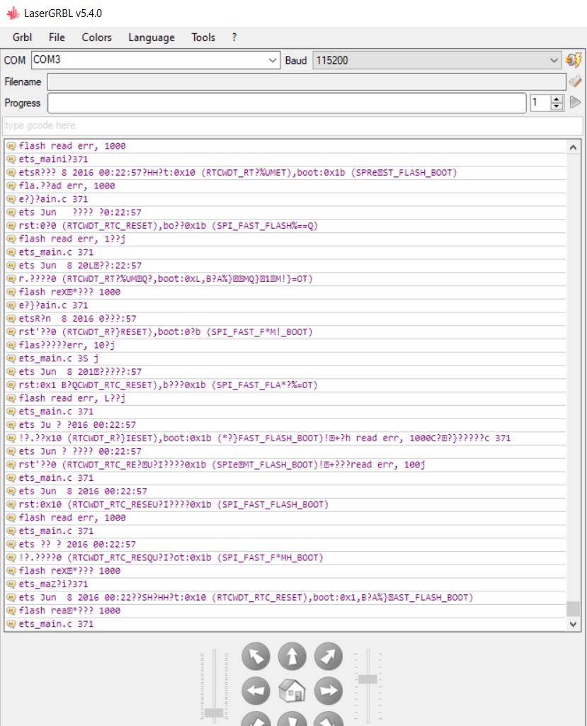
That would have been the perfect solution for me, though it seems that I have some trouble flashing the firmware.
After flashing the bin file I can’t connect to the board through LaserGRBL and the screen is black. Flashed a different file and all works fine.
Am I missing something?
Would have configured the file like suggested, but I don’t have the know-how so maybe a walkthrough (step by step) could help me solve the issue…
Would appreciate the help. Thanks.
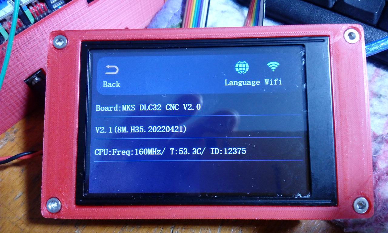
OK…but it can easily be a very deep rabbit hole. I said I tried loading the firmware onto a spare ESP32, so I never tried it with a display. Looking a bit deeper into it I noticed the firmware I linked as supplied was setup for a coreXY machine, so I edited the machine.h file to use the i2s_out_xyz_mks_dlc32.h" profile instead of the i2s_out_corexy_mks_dlc32.h profile, I then loaded it onto my mks dlc32. The firmware reports as being 8M.H35.20220421 so it is a quite recent firmware for a 3.5" display. The display firmware is characteristically (for MKS) incomplete but semi-functional. If you can put up with that (you really don’t need the display at all) then the file firmware.zip (758.7 KB)
can be flashed onto the dlc32 using any esp32 flashing tool (the tool provided by MKS or Espressifs own esp32 flash download tool or PlatformIO for example)
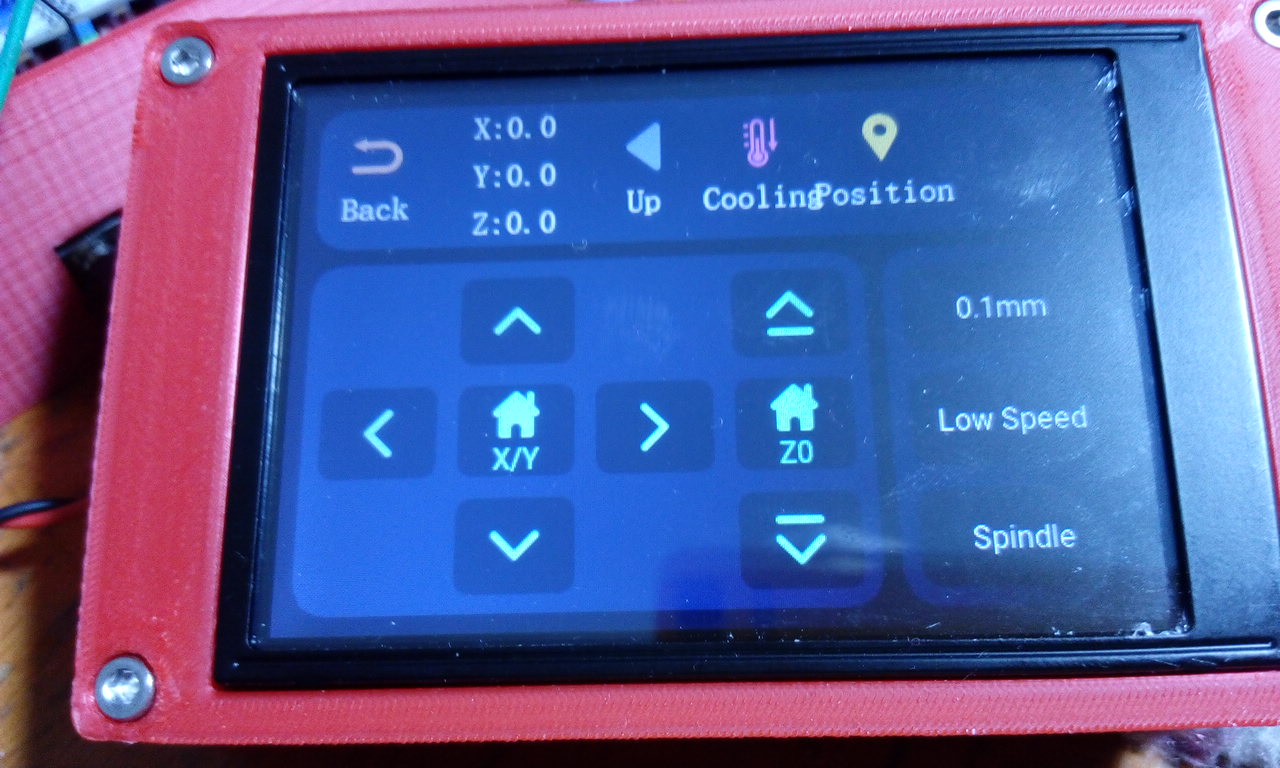
Grounding pin4 halts the program as shown in the vids.
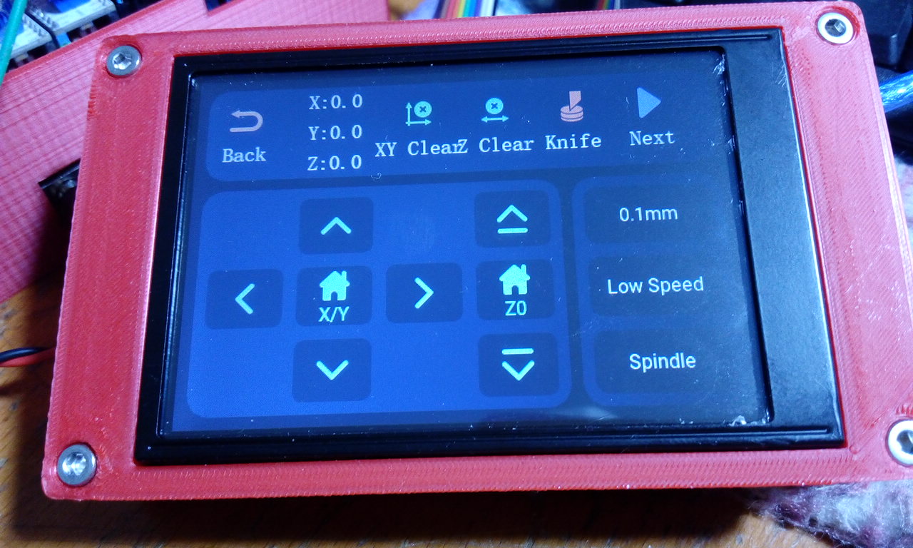
The ‘knife’ icon runs the probe routine. I could not get it to pass but I am not connected up to a physical machine so the timing of my probe inputs may well be way off causing the failure.
The cooling icon does nothing (because we have stolen the mist cooling pin)
The ‘spindle’ icon turns the laser/spindle on 100%
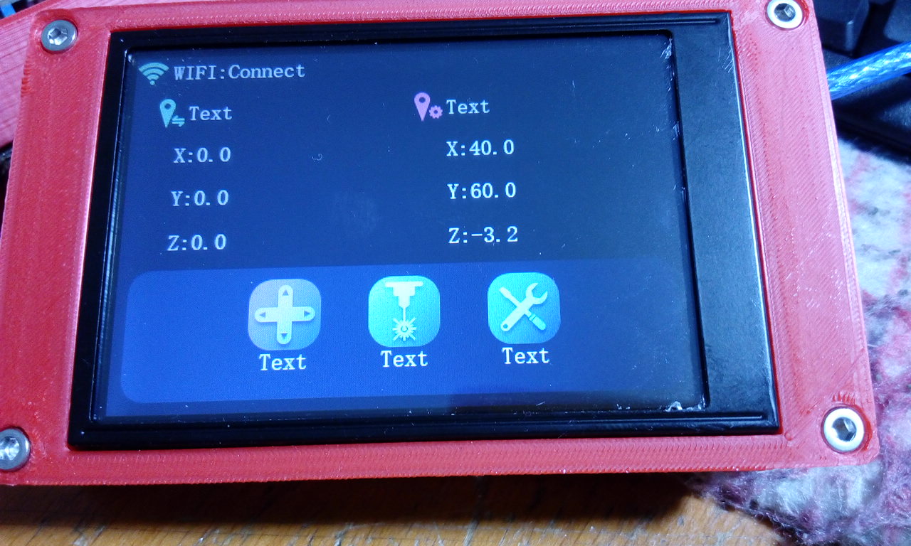
The ‘position’ icon seems to set X0Y0Z0 - the same as XY Clear and Z Clear
I believe there is editing software available somewhere to edit the menus but that is another rabbit hole!
If you need further help please be specific.
First of all, that’s AWESOME! I’m inspired by just reading your replay and seeing your work.
That’s exactly (!) What I needed and what I’ve been looking for.
But, I don’t know why, after plashing my MKS DLC32 v2.1,
I get this:
MKSLaserTool 2.1.5 is a different utility altogether, it is supposed to be for editing the icons and texts within the firmware. I would try V1.0.6 if I were you, I know that version works for me whereas I cannot get V2.0.4 to work at all.
I have only made a couple of changes to the stock firmware as supplied and I have successfully uploaded the modified firmware onto my dlc32. Try compiling the stock firmware from here and flash your dlc32 using the v1.0.6 tool from here
I didn’t read anything past the question but I wouldn’t use a software solution. Grab a 24v/110v relay to plug the router into, then put a switch inline so the relay powers down as soon as the door opens. No lag, no delay, no software issues, a physical disconnect.
I have built a custom cnc mill and was wanting to do a similar thing here but have a mks dlc32 Max. This has a built in door switch input on the board which I hope will work as a feed hold and shut off the spindle. I would like to add a resume input also. Can the fire detection input be used for this task? I was hoping to use grblHAL as I intend to add a 4th axis for simultaneous machining. Any help or pointers would be amazing.