One other annoyance with Klipper firmware is that it does not like G01, G02 or G03 and probably not any of the other G-codes less than G10 with the preceding 0. It wants the codes to be G1, G2, G3 etc. It is easy enough to globally replace the codes in Notepad++, but none the less annoying. I notice Sandify & Estlcam generate the G01 instead of G1, but PrusaSlicer generates G1 codes. Is it more the Cam type software that pad the numbers? I posted a similar message on the klipper discord & see what they say.
Interesting. I didn’t know that.
It would be easy for me to change it. But I don’t want to break anything that only accepts G01, if that is a thing.
It definitely seems like Klipper should be able to handle G01, since it is the high level that does the parsing. But oh well. Easy fix.
@bobnik, check out your web coming to life on a new machine!

Until recently, OctoPrint gcode viewer also expected G1 and choked on G01 (it’s since been fixed  ).
).
Apparently it’s an unspoken 3D printing convention that no slicers deviate from.
As the lines between 3D printing and CNC get more blurred, Klipper and similar just need to be able to tolerate it.
Someone on the klipper discord seems to have given me the answer. I will try it today. I was on the right track, but had not found the correct syntax to use for the Macros. He referenced this thread.
Accept CNC gcode variants · Issue #4015 · Klipper3d/klipper · GitHub
The rawparams option has since been added to klipper since the above message.
gcode_macro: Add “rawparams” pseudo-variable by pedrolamas · Pull Request #4727 · Klipper3d/klipper · GitHub
Also Jeff, is it possible to add an option in Sandify to use the G2 & G3 arc commands instead of series of G1 commands? The segments are probably not noticeable on sand tables, but can be quite apparent on plots. It can also make the G-code files a lot smaller. Not a big deal for me, but might be a useful option.
Here is the macro code I will try. I currently only need the G00, G01, G02 & G03 macros
[gcode_macro G00]
gcode:
G0 {rawparams}
[gcode_macro G01]
gcode:
G1 {rawparams}
[gcode_macro G02]
gcode:
G2 {rawparams}
[gcode_macro G03]
gcode:
G3 {rawparams}
[gcode_macro G04]
gcode:
G4 {rawparams}
[Edit] I just tested the G01, G02 & G03 macros & they work perfect
Ok. I will change that soon (we are overdo for a release).
The arcs are harder. Everything in sandify is x,y vertices. So I have two ways to fix it:
- Update all the transforms, effects, outputs, machine limits, and preview to accept arcs as well as vertices. Then update all the shapes to use arcs when they have them. The heart for example could be two arcs and two lines. The big trouble there is the effects affect the whole arc, and would need to be broken into smaller pieces again. It would be a huge change. A lot of interesting problems and math though. There are probably some shortcuts.
- Adding some code on the output that can recognize an arc and then fit a G2/G3 to any set of vertices. That would have to be clever and still needs to respect the machine limits and be shown in the preview, so maybe only half the work (or a bit less), but it also would be imprecise.
I also use the same resolution for the kernel shape at any size. That is just the nature of the code. I could try to set the original resolution very very high (2048 vertices per arc, or whatever) and then try to reduce the number of points later.
All these are more tricky than the first fix. I have been thinking about it for a while. Mostly because adding more vertices really slows it down. It would be a lot faster to keep everything as arcs and just manipulate them, instead of manipulating 128 vertices.
Looks like you have been thinking about this for a while. Curvilinear geometry usually throws me for a loop. I have a piece of openscad code that computes the intersection points of a line and an arc if that would be of use to you. My boss 20+ years ago helped me with that problem in AutoCAD lisp & I converted that formula to openscad a few years ago. You probably already know this, but there are usually 2 possible solutions to the equation unless the line is tangent to the arc. The routine requires these parameters, X & Y coordinate of arc, start and end X & Y coordinate of line and Radius. Since there are 2 possible solutions to the problem, you will have to use the start and end point of the arc to determine which coordinates to use. I just tested it again to see if it worked the way I remembered it. I went to 8 decimal places for the answer to be accurate to 2 decimal places. With 4 decimal places it was off by around 0.2. The openscad code for the formula is only 13 lines.
Super cool!
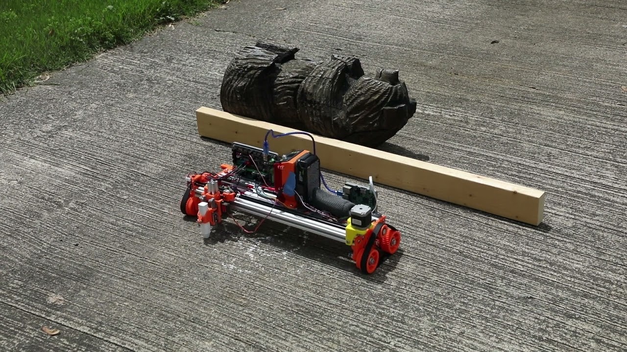
First Chalk test was not very good. Maybe using servo to move chalk down along an arc rather than straight up & down like I saw one other pen plotter do.
Needs some extra spring force so the chalk keeps in contact while it’s being ground down.
It does have springs, but they are light duty springs from a pen. With using the servo, probably can’t use stronger springs. The movement distance is around 5-6mm & I set the bottom of the chalk when in up position to 2mm above surface using a popsicle stick for feeler gauge. It did wear the tip of the chalk down 3/8" after my 3 test runs. Maybe I should look into a way of dropping sand or bird seed like that sand machine I referenced uses. Even if I get the chalk to work better, seems like it will wear down to quickly to work for any descent size design. I thought the wearing of the chalk would probably be a problem. At least the wheel drive system now works reasonably well.
Okay I know this is getting ahead of things here but if you made a little vacu-formed hood for it…sexy. Bare minimum great excuse for new vacuformer project.
I don’t follow you here. Can you elaborate? I am starting to think that some easy open valve with a reservoir above it filled with sand whereas the valve could easily open & close with a servo. This is probably similar to that sand machine.
I was just thinking a cool looking hood. Keep spectator fingers out. Maybe some big googly eyes.
Got Ya. I am all for making it more fun looking. Will see if I can get it to work outside 1st before managing all the wires & electronics connections.
They make sidewalk paint. I wonder if that would be easier. Are there sidewalk markers?
Or, my first thought on a mechanical solution for the chalk was to let it ride on a long slide (which it looks like you already have) and then weigh it down by putting a bag of beans (think corn hole) on the chalk. You still would need a bigger servo to lift it, I guess.
The asphalt also looks a little rough. Maybe there is a place with smoother concrete? But that may mean limited utility.
Another thought I had when watching that is that maybe you could intentionally create designs that had a bit of a wave to them. Just some fluidity. Just enough so you wouldn’t care if it was a little wrong.
That code is useful. But the real labor is handling all the cases. The limits code actually took a lot longer than I thought to work in a fixed circle or a rectangle. Just because there are a lot of corner cases (literally) that come up.
I hope to get there one day. And if I was doing it as part of my job, it might be the first thing I would change. But it is just a spare time hobby at this point. It trucks along and gets the job done.
I wouldn’t mess with the code unless it is something you want to do or more important if it isn’t fun, don’t do it. I think the sand reservoir is the way to go as that has been shown to work and uneven pavement would not bother it. I could try the chalk on an asphalt bike path nearby but seems like the chalk will wear down too much. I do have some thinner chalk, but they seem to brittle to hold up well. The thinner chalk I would not have to worry as much about it wearing down but would have to make sure it stayed in contact with pavement. I looked up the chalk paint earlier and looks like it might be hard to get off. I will think about a little more before delving into a design for it. Thanks for the feedback. I am really tempted to redesign the wheels for a wider belt but want to follow thru with the sand idea first as that was my original goal & the machine seems accurate enough for that.
This, coupled with something that actuates a clamp for Pen-Up moves. Issue an M7 or M8, I think, (think air-assist) command, to actuate the clamping action before every Z raise command. The Z raise distance could be fixed (I think not more than 2mm would be needed), the chalk will wear, but the tip would always be the same distance relative to current Z level when the clamp engages. Then dis-engage the clamp (M9) just before, or after maybe, (I’m sure two consecutive commands seemingly happen at the same time to us slow humans) Z lowers.
There is probably some way to do it, but I can’t grasp it yet.
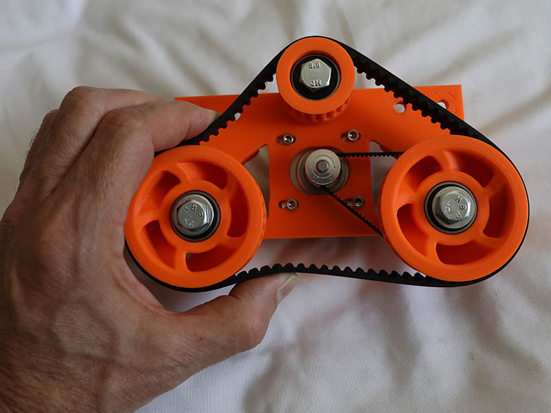
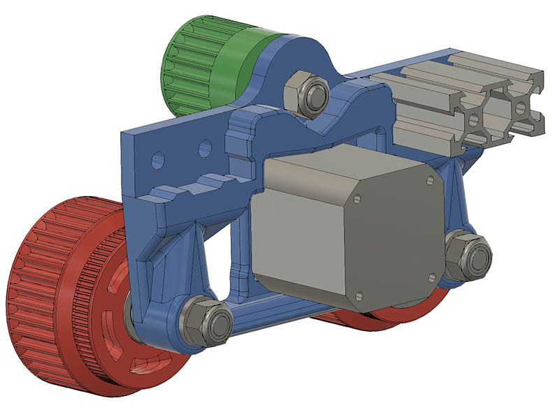
Meanwhile, I am revisiting the Wheel plate design. I used the pitch angle for the HTD5 belt for measuring the belt connections but seems like it is looser than it should be. This image has the top idler pulley at its upper most adjustment. It was sized for the belt to perfect length at middle spot (3mm adjustment on each side of center) Maybe these were measured by inside diameter.
I am thinking that if I can get the HTD5 belt tighter, the accuracy might improve. I moved the idler pulley hole up 3mm. I am printing the parts with PLA+ with 5 Perimeters & 40%infill. I was going to print the final versions with more infill, but didn’t get around to it. This should beef up the support around the top idler. A little over 4.5 hour print with 6 Perimeters, 70% infill & adaptive from .2 to .28 layer height.
Someone on the openbuilds forum, showed me this option for chalk. I had looked at this yesterday, but the one I looked at warned about not washing off easy.
Amazon.com: Testors Spray Chalk, 4 Count : Everything Else


