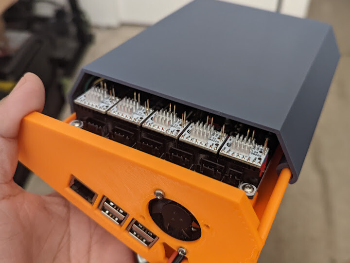
if you have a dremel you could trim them a bit or sand your top case so your drivers can fit nicely.
5 Likes
Or wait for them to heat up enough to melt into the top, providing another positive locking mechanism… 
2 Likes
Case looks great! Was looking for something similar for a SKR 1.2 and RPi4. Love seeing creative thinking!
2 Likes
Lets see how these perform. I’m not sure what I’m going to do with the other 95 from the variety pack. Maybe I can double stack them. 
1 Like
Now I don’t remember wherw I saw it, but someone uses those little heatsinks as stand-offs for using a laser in order to be able to cut through material.
1 Like
Dki4linux did. In one of the neje threads.
1 Like
Awww… How cute! Widdle, itty-bitty heat sinks… 
Looks like you even have room to run a copper heat pipe across all of them and out of the case. 
1 Like
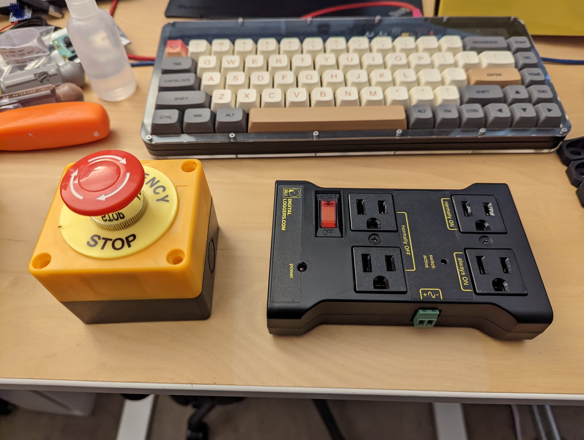
More goodies! The plan is to use the always on socket to power the Pi/SKR, the 2 switched sockets for the router and the vacuum and place the emergency cutoff on the main AC line. The switched outlets will be controlled by an extra I/O pin from the SKR.
Since klipper (klippy actually) can address "MCU"s over USB, I’m thinking of loading klipper FW on this little Arduino based macro board to use as a jog controller. Just need to replace the key caps with arrows, and decide what to use the other 2 buttons for.
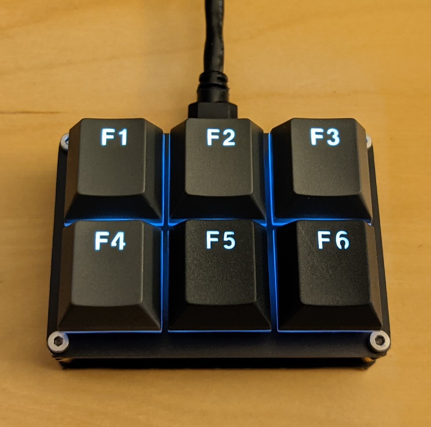
If you are wondering, it’s a nice little open source PCB from:
4 Likes
Nice! They didn’t used to have an always on. Only two normally on and two normally closed.
2 Likes
I’ll just leave this here for future “klippers” that do not want to spend way too much time researching bootloaders.
My thought of using a small opensource keyboard as a jog controller with klipper hit an immediate speedbump. The beauty of klipper is, the firmware itself is relatively small and installs on a ton of microcontrollers. It’s so small because it’s only job is to turn the microcontroller and all if it’s attached devices into simple drone that does what the control process (klippy) tells it to. Kliippy, running on a python compatible computer (Pi or PC), talks to 1 or more of these “MCUs” over a serial/UART connection making it interestingly expandable by just flashing klipper firmware to the device, defining the new MCU in your printer.cfg (text file), and restarting the klipper processes on the computer. The only time you have to “update” the firmware on the device is when there is a major change to the “drone” code which is rare. Sorry, this turned into a klipper fanboy post.
Back on topic. My little six pack keyboard uses an Arduino Pro Micro running QMK firmware when attached to my computer as a macro-board. Converting this to klipper should have been as easy as compiling the firmware using klipper’s make menuconfig command, selecting the options below, then running make to compile the new .hex file.
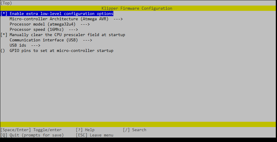
I then flash the new firmware by hitting the reset button on the PCB and use the avrdude utility to do the deed. This is what should have happened. It should have been quick and easy… it was not. It’s ok though, every challenge is an opportunity to learn something new and in this, I leaned a bunch about bootloaders.
The Pro Micro uses an Atmel atmega32u4 AVR. These boards usually ship pre-flashed with a boot loader called “caterina”. The purpose of the bootloader in this case is to allow you to reprogram the chip without needing additional hardware like an in-circuit serial programmer (ICSP). When you bridge the ground and reset pins, the MCU will “boot” into this bootloader instead of the program you had previously loaded. When the MCU powers up normally, the bootloader does nothing but load the flashed program.
The atmega32u4 only has 32k of flash space. The carerina bootloader consumes 4k of that space leaving 28k in useable program space for klipper. Why is any of this important? A little while ago, klipper grew just past that 28k mark. This means that uploads fails and my face looks like this  .
.
At this point I have 3 options based on a bit of googling.
- Beg the klipper devs to somehow make klipper even smaller
- Pros: I could continue to use and update firmware with no extra steps or hardware.
- Cons: Unlikely to happen
- Flash klipper directly using an ICSP
- Pros: This removes the bootloader freeing up the space needed.
- Cons: Anytime I need to update the firmware, I need to remove the MCU from the keyboard and attach it to an ICSP.
- Replace the 4k bootloader with something smaller.
- Pros: I could continue to use and update firmware with no extra steps or hardware.
- Cons: Need to use an ICSP at least once to replace the bootloader. Klipper’s flash mechanism may not understand how to trigger the programming mode increasing the logical number of upgrade steps in the future.
After much trial and error, I opted to replace the bootloader with a nice compact 1k version called kp_boot_32u4. Since I have a few Pro Micros in my bin, I was able to turn one into an ICSP using a handy sketch that comes bundled with the Arduino IDE. This tutorial does a much better job of explaining things than I can.  After the new bootloader was flashed, I used the keyplus flasher to upload the compiled klipper .hex file. This worked like a champ! I finally had klipper running on this little sucker.
At this point, I have all of the pins mapped out for the 6 keys, the LED matrix, and the onboard TX/RX LEDs . I have gcode buttons defined to toggle the onboard LEDs as a test case. Once I get everything installed, I’ll look into the macros needed to properly jog the machine. The backlight LEDs are in a “charlieplex” matrix and I’m not sure that klipper can intelligently control them like it does for RGB LEDs. For now I just have them all lit as an indication that klipper has initialized the MCU.
Here is what I have so far. Just add [include six_pack_controller.cfg] to your printer.cfg.
#####################################################################
#   Six Pack Key Control
#####################################################################

[mcu ctrlr]
serial: /dev/serial/by-id/usb-Klipper_atmega32u4_12345-if00
restart_method: command

#####################################################################
#   Pin Mappings
#####################################################################
#          Key Map                LED Grid
#      [PD4][PC6][PD7]         [PF6][PF7][PB6]
#      -MX1--MX2--MX3-    [PF4]-MX1--MX2--MX3-
#      -MX4--MX5--MX6-    [PF5]-MX4--MX5--MX6-
#      [PE6][PB4][PB5]
#
#                 Bottom Header
#  VCC  TX   RX   GND  SDA  SCL  PB1  PB2  PB3
# [VCC][PD3][PD2][GND][PD1][PD0][PB1][PB2][PB3]
#
#                   Pro Micro
#                 RX_LED TX_LED
#                 [PB0]  [PD5]

[board_pins pro_micro]
mcu: ctrlr
aliases:
    TX0=PD3,   RAW=<RAW>,
    RX1=PD2,   GND=<GND>,
    GND=<GND>, RST=<RST>,
    GND=<GND>, VCC=<VCC>,
    PIN2=PD1,  PINA3=PF4,
    PIN3=PD0,  PINA2=PF5,
    PIN4=PD4,  PINA1=PF6,
    PIN5=PC6,  PINA0=PF7,
    PIN6=PD7,  PIN15=PB1,
    PIN7=PE6,  PIN14=PB3,
    PIN8=PB4,  PIN16=PB2,
    PIN9=PB5,  PIN10=PB6,
    RXLED=PB0, TXLED=PD5

#####################################################################
#   Button Config
#####################################################################

[gcode_button mx1]
pin: ^!ctrlr:PIN4
press_gcode:
    SET_PIN PIN=_rx_led VALUE=1
release_gcode:
    SET_PIN PIN=_rx_led VALUE=0

[gcode_button mx2]
pin: ^!ctrlr:PIN5
press_gcode:
    SET_PIN PIN=_rx_led VALUE=1
release_gcode:
    SET_PIN PIN=_rx_led VALUE=0

[gcode_button mx3]
pin: ^!ctrlr:PIN6
press_gcode:
    SET_PIN PIN=_rx_led VALUE=1
release_gcode:
    SET_PIN PIN=_rx_led VALUE=0

[gcode_button mx4]
pin: ^!ctrlr:PIN7
press_gcode:
    SET_PIN PIN=_tx_led VALUE=1
release_gcode:
    SET_PIN PIN=_tx_led VALUE=0

[gcode_button mx5]
pin: ^!ctrlr:PIN8
press_gcode:
    SET_PIN PIN=_tx_led VALUE=1
release_gcode:
    SET_PIN PIN=_tx_led VALUE=0

[gcode_button mx6]
pin: ^!ctrlr:PIN9
press_gcode:
    SET_PIN PIN=_tx_led VALUE=1
release_gcode:
    SET_PIN PIN=_tx_led VALUE=0

#####################################################################
#   LED Config
#####################################################################

[output_pin _rx_led]
pin: !ctrlr:RXLED
value: 0

[output_pin _tx_led]
pin: !ctrlr:TXLED
value: 0

[output_pin _sp_row1]
pin: !ctrlr:PINA3
value: 0

[output_pin _sp_row2]
pin: !ctrlr:PINA2
value: 0

[output_pin _sp_col1]
pin: !ctrlr:PINA1
value: 1

[output_pin _sp_col2]
pin: !ctrlr:PINA0
value: 1

[output_pin _sp_col3]
pin: !ctrlr:PIN10
value: 1
7 Likes
How is it going with Klipper? Any issues? Would like to do Klipper myself, are you willing to share the printer.cfg?
2 Likes
Any updates on this would be great! Been searching all the posts for klipper configs to see what approaches work for everyone.
Sorry for the lack of updates. Work has been busy non-stop for the past few months. Unfortunately, I have not made much progress since my last post. Klipper runs fine and the system homes and jogs just fine, but I have yet to build a table so I have no idea how it performs.
Once I have put blade to wood, I’ll post my final configs.
2 Likes
In the meantime, here is the link to my remixed case. I hope someone finds it useful. ![]()
1 Like
Nice!