Revnull LR3 Build, my 1st CNC

I do not know why it is so strange for me to see a box I packed on the other end unpacked. Why do I remember them all, I have packed thousands of boxes?

I like to repurpose all the packing materials I can. I still recycle a absurd amount of material, but I reuse anything I can that is clean. Lots of filament bags. Still can’t find anything to do with old spools though.

5 Likes

Today’s amazon gift, screws! No more mixing whatever I could find in my parts bin. Philips, socket head, and button head of different lengths. Now everything is a stainless steel button head. Woohoo for consistency!

While experimenting with my jumble of screws, I found that M5 x 25mm worked better for most of the YZ assembles. The 30mm screws protruded a bit too much past the nut for my liking, but that’s just me being nit picky. :wink:

The last bit I’m waiting for are the wires and spade connectors for my endstops and M2.5 x 12mm mounting screws for the same.

2 Likes

You know, when I built my mpcnc I never knew hardware was soooo expensive. I do not buy much bulk screws/bolts. It really went up!

1 Like

I couldn’t wait for the endstop screws to arrive. I put everything together this evening. I know that I will have to strip things down again, but I’m super happy with how this is all coming together so far.

5 Likes

This morning I migrated my klipper test setup (rat’s nest of wires on my desk) over to my work bench in preparation of stepper testing. I took this opportunity to re-wire the Pi to use the local UART and power from the “AUX-1” port of the SKR 1.3. I think this 350W PSU is overkill, but I had it on hand. Maybe I can power a 24vdc laser at some point.

Has anyone used a DIN rail on the back of the LR3? I think it would be both ridged and provide additional mounting options for controllers and power supplies.

1 Like

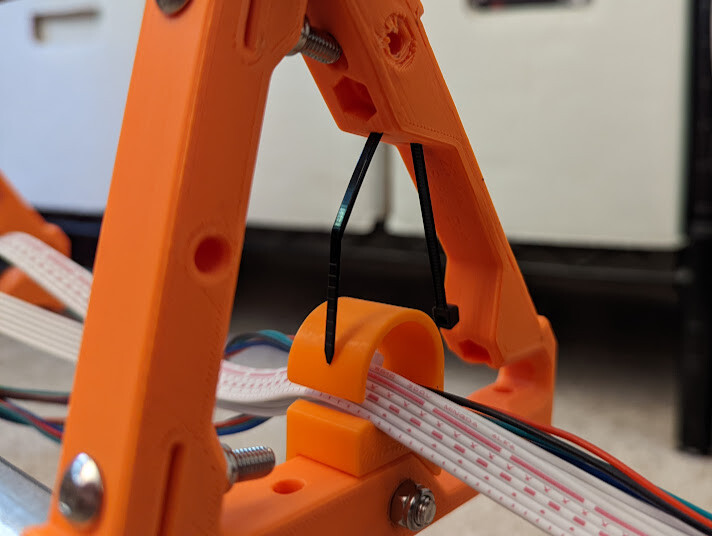
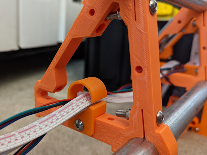
While looking for ways to route cables from the far side of the gantry to the other, I found myself wishing there were built in routing channels inside the braces. I thought this was a perfect opportunity to contribute in to the project in a very small way. I modeled up a C channel that uses the open screw hole at the bottom of the brace to mount. It seems to work well.

Then @vicious1 pointed out something that I never noticed… the zip-tie loop modeled into the top of the brace. Well damn :exploding_head:

6 Likes

Thanks to @vicious1 & @jeffeb3 for the awesome case remix! I think it’s going to fit my SKR 1.3 and Pi perfectly.

I installed my endstops this morning and found that the Z axis endstops are not triggering. The instructions states that if that happens, you can bend the lever a bit. I feel like I would never get them bent consistently. Also, if I ever need to swap one out, I’d likely forget to bend it and grind something. :slight_smile: I’ve remixed the endstop mounts to lengthen them by 3mm. The slot is also longer for additional adjustability.

image

2 Likes

Please don’t run that board on top of a conductive bag. It might never have an issue, or the electric pixies might decide they don’t like you and fry the board.

1 Like

Hi Barry, thanks for the heads up. I know “I’ve been doing it for 20+ years” is not a good excuse, but that antistatic bag has a significantly lower chance of shorting something than the solder sprinkled silicon mat underneath it. I guess I should just clean my work bench. :wink:

1 Like

Well, a 3mm extension was still too little to hit the right trigger point.

I’ve now extended it to 6mm. I see how it fits after work.

The controller case is finished! The fitment between the base and the lid are a little loose, but I think once the screw is in the end, it should be fine. I was worried about extra noise from rattling, then I remembered what I’m building. :slight_smile: #ThereWillBeNoise

1 Like

Bending the tabs is fine, you will never adjust or bend either of them perfectly, that is why we adjust the endstop offset later. You will pretty easily get the Z level to under 0.2 mm over 4’ in a couple tries.

2 Likes

Oh absolutely, but I know me. If I have to ever replace it, I will forget to bend the new one then proceed to break off the lead screw holder as it overshoots on homing. The small modification to the endstop holder is better for my particular brand of forgetfulness. If I get it to work and others find utility in it, I can post it for public consumption, if your license allows (I still need to read it).

1 Like

Nope, the steppers will skip. That is a part of the reason not to use Giant Nema 23’s.

Absolutely

2 Likes

It seems like 6mm extension was the trick. :slight_smile:

I’ve posted them on printables if anyone else can use them.
https://www.printables.com/model/252250

4 Likes

Hi

Is this case remix generally available?

1 Like

I printed and glued a little landing for the XZ plate finger to make the switch hit a bit better.

2 Likes

I’m not sure about generally available, but @jeffeb3 post a link to it in the thread below. I had to create an Onshape account to access the project and export the STLs.

3 Likes

This morning I was determined to get this thing to move. The Pi ZeroW fits well in the space and has room for a micro USB power connector, but the GPIO headers and a little too close to the SKR to use standard dupont connections. :frowning: I guess I could remove the header pins and solder directly to the PCB, but that feels a bit permanent for my liking.

There were a hand full of times the load was a bit high so I thought I’d try a 3B+. The SKR’s 5vdc regulator seems to have enough extra mA to power the ZeroW, but the the 3B+ was throttling and under-volting so an external buck will be required. I’m a bit perplexed on how to power this thing since the micro USB power port is blocked and the BPIO header is too tall. I think additional remixing will be needed. Maybe add a couple of mounting holes for the buck. :slight_smile:

The SKR 1.3 fits like a champ! Though pictured, I had to pull the 3B+ out of the case until I can find a way to power and cool it in the existing case. @jeffeb3, any suggestions?

3 Likes

I am using an external buck/boost converter and I soldered straight to the 5V and GND of the input power micro usb. That way, the pi uses its own circuitry to filter the 5V a little.

2 Likes

It lives! Albeit a bit squeaky at the moment. I’ve been able to translate most of the V1 marlin changes into klipper (as far as I can tell) and it moves where I tell it to. Time to build a table I guess.

5 Likes