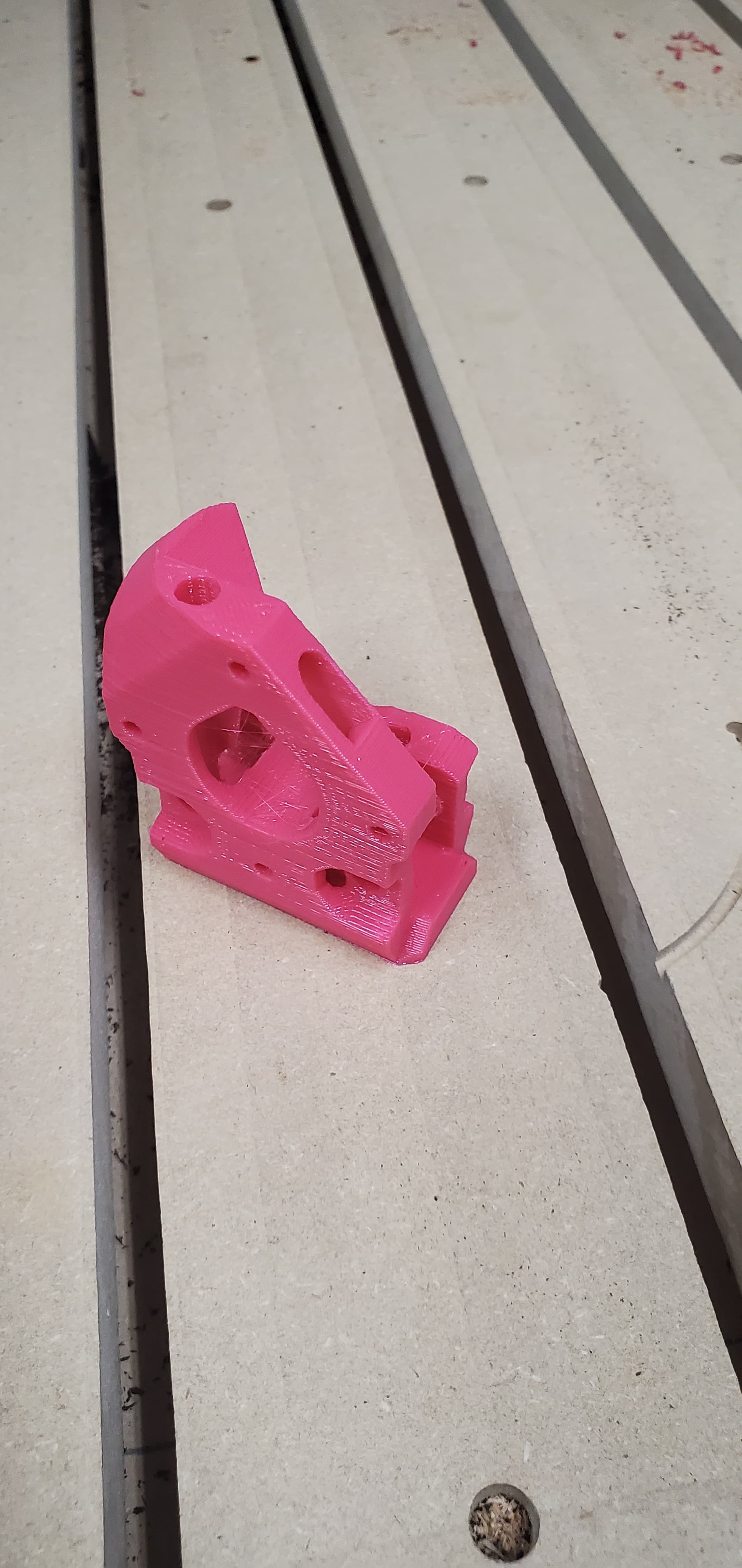
Aside from the stringiness, I’d say not bad!


5 Likes
Printing, and streaming…
Expect buffering and crappy quality, our ISP (Comcast) is having issues this week.
3 Likes
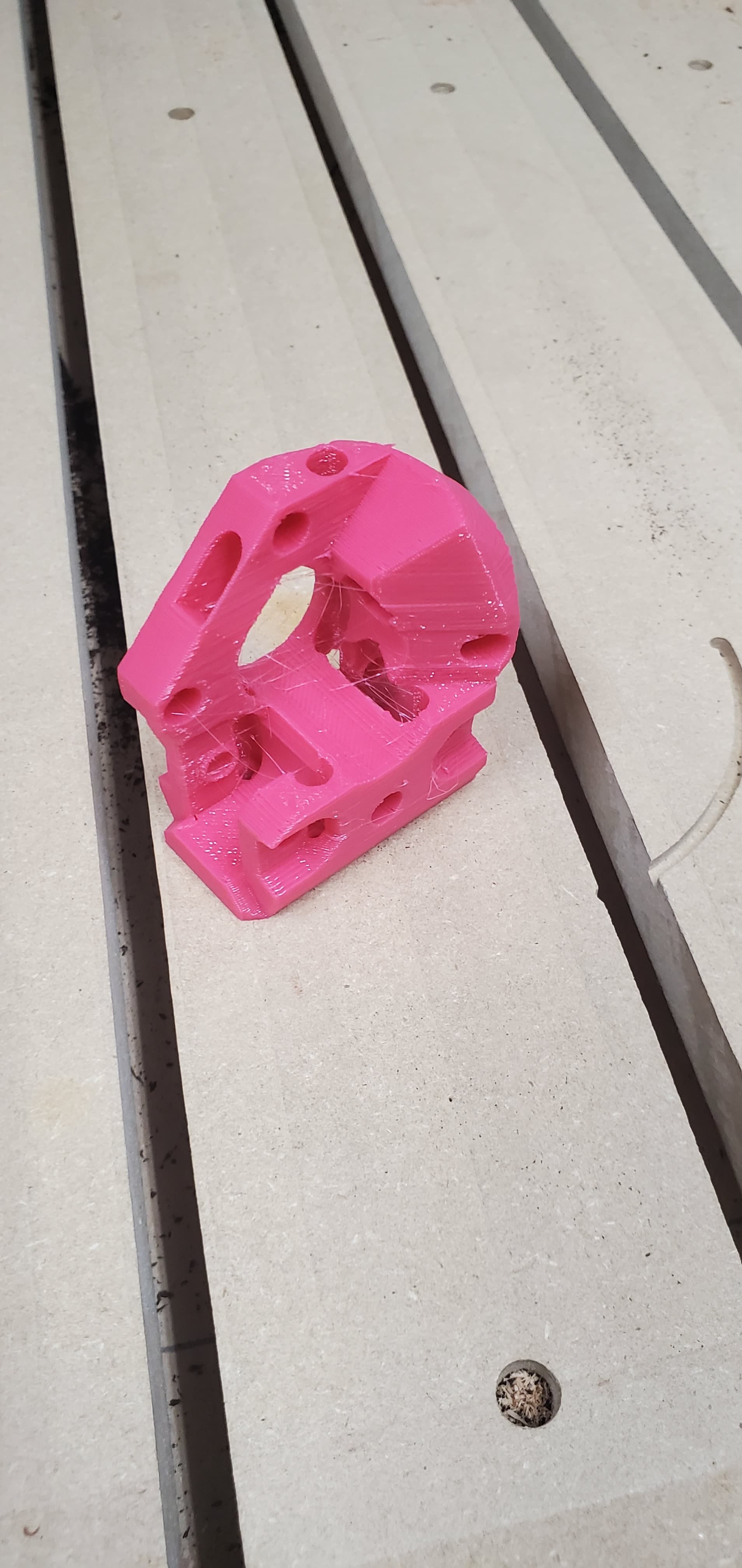
Swiss Z post print done. Posted close up viewing :

0.6mm nozzle, 0.32mm layer height, mostly stock Ender 3 Max, fresh Overture silky PLA. 60% infill, almost same profile used for LR3. Need to check if my screw drivers are skinny enough to fit the deeper holes.
Repeat V2 looks cool. Been wanting to build a more capable Core XY. Got Repeat V2’s goals (and non goals) listed somewhere? What would be a comparable commercial 3D printer?
4 Likes
@vicious1 I had bought rails, bed, octopus board, etc for repeat v1, but I didn’t get on it right away while my wife was pregnant with our first and since having her I haven’t touched it. Was just looking to get back into doing things with the parts and I’m seeing repeat v2. How close are we talking? No pressure as I really appreciate that you’re doing the hard design work here… 
At this point I think I’m definitely going to wait. I bought a 300mm bed so it would be that size, I think the rails are 400mm and could be cut down.
M3’s use a #1 driver. All of mine are skinnier. Shoot I did not think much about that.
Well it is fully functional, and prints well…better than the V1. So I could release it today but I want to make sure print-abuility is there and I am not missing anything. I think I will get the basics out in a few days. Firmware and any sort of bom beyond the CAD model is definitely after vacation. Well, if things go well I might get the firmware in the builder.
Definitely wait, and I have found my angle grinder with a cutoff wheel works far better than anything I have tried at cutting the linear guides/rails.
2 Likes
There are a bunch, a #1 driver is required. 6.75mm diameter max.
1 Like
Thank you guys for printing them. It helps me a lot to see how they are turning out. I am making parts far more intricate on this one so a well tuned printer is needed. I will be suggesting people run through teaching tech’s tuning guide before this one. That Z post is by far the most tricky so I think everyone will need to start there as a test.
4 Likes
Not a big deal to fix it in the slicer, but did you ever figure out why some parts are way off the origin when placed in some slicers (Cura 5.1 in this case)?
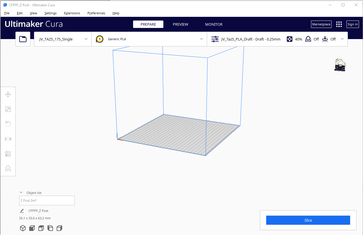
2 Likes
Yeah observed this as well, for the swiss Z post, and many of the LR3 models. Even mistakenly printed a model that was partially ‘submerged’ below the Z axis.
3MF seems to keep things like part origin in the file, but I can’t find any info on that. I can just save them all as standard STL’s if that is easier.
Could there be a setting in cura to disable incoming location or center parts by defualt, maybe, since the other standard slicers do not do it?
1 Like
I thought they were in a funny place in prusa slicer too. I just hit the auto layout button to suck them back to the center every time.
I don’t remember them being too far away. Just not centered.
2 Likes
I just dropped some parts on there a few minutes ago, so far so good. I will keep an eye on it to see if there is anything I can do easily.
3MF keeps a lot of information, and is(or rather it supports) a “tighter” mesh structure than STL files, so you might get better resolution parts from it.
I find this happens to me when I export 3MF mesh files straight from Fusion360, it keeps the origin information from Fusion. If I have done the part as its own thing, and then rotate and position it in an assembly, it depends on where I exported the .3MF file from as to what Prusa Slicer takes as the origin. It could sometimes be the origin from the file where I created the part, and it could be the origin of an assembly that uses the part.
When using 3MF files, it’s a good idea to “fix” the origin anyway. 3MF files can be exported from many slicers which is nice as a parts layout, but sometimes is troublesome if your print bed is not hte same size as the one that the person who createed the layout has.
1 Like
I will resave each part in a slicer before I release them to be safe.
Odd that some of them are not 200-300 mm off the mark. I model them in sets so they are usually very far from the origin. Some sort of normalization is happening I am just not sure what.
1 Like
So, I have not been paying attention teach, is there a cliff notes to the v2 changes??
Same same, Just no CF tube, Linear rail instead.
I Just could not let it go. I added a few more tweaks to that Z post part.
1 Like
What I’ve caught so far:
Linear rail as X axis instead of square tube and rollers.
Z motors ride up and down with bed, which saves space.
Extrusion frame is plan A, instead of using a box made from mdf.
And by far the most innovative, the stepper drivers are mounted on the X carriage!
![]()
![]()
4 Likes
Would that count as passive driver cooling?
1 Like
LOL, funny. Was bewildered and confused for way too long, before remembering today is fun Friday.
Is the linear rail just suspended at each end, with no other support? Looks neat, or is the rail mounted to angle-bracket, I-beam or something to reduce Z deflection/vibrations and help dampen ringing?
1 Like