Hi I have no idea what I’m doing with this wiring I’m by far no electrician of any kind, however I have followed all the instructions and seem to be stuck with wiring the power supply to my control board. Also bought the LCD not really sure if that has anything to do with it but anything helps! Thanks in advance.
For wiring power to the control board, see the Power header in Rambo 1.3-Rambo 1.4 section of this page. Power needs to come to the board in two places…one for the logic and one for the motors. This can be done with a couple of short sections of wire looped to the connectors creating a parallel connection as in the picture at the link. It is suggested to just cut off the barrel connector on the power supply and wire to the board directly.
You’re going to have to simplify that me to common English lol. Do you have any pictures by chance? I’m a visual learner
Let’s break it down.
1A) If you have a voltmeter or other way to determine which wire is positive. Cut off the connector at the end of the power supply wire, strip some of the casing from the wire, then strip the insulation from the two wires on the end. If the wires are red and black or white, then the red will be positive and black /white will be negative. If they are not these colors, you will need to use your voltmeter to test and figure out which wire is positive.
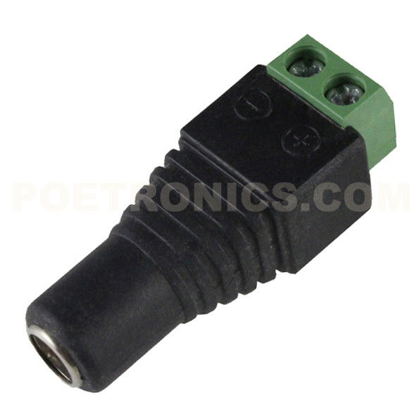
1B) If you don’t have a voltmeter (or just don’t want to cut the wire), then you can use a connector like this one. I had one provided with my kit from V1, but that was years ago, so I don’t know if they still ship one. Note how the connector is labeled positive and negative.
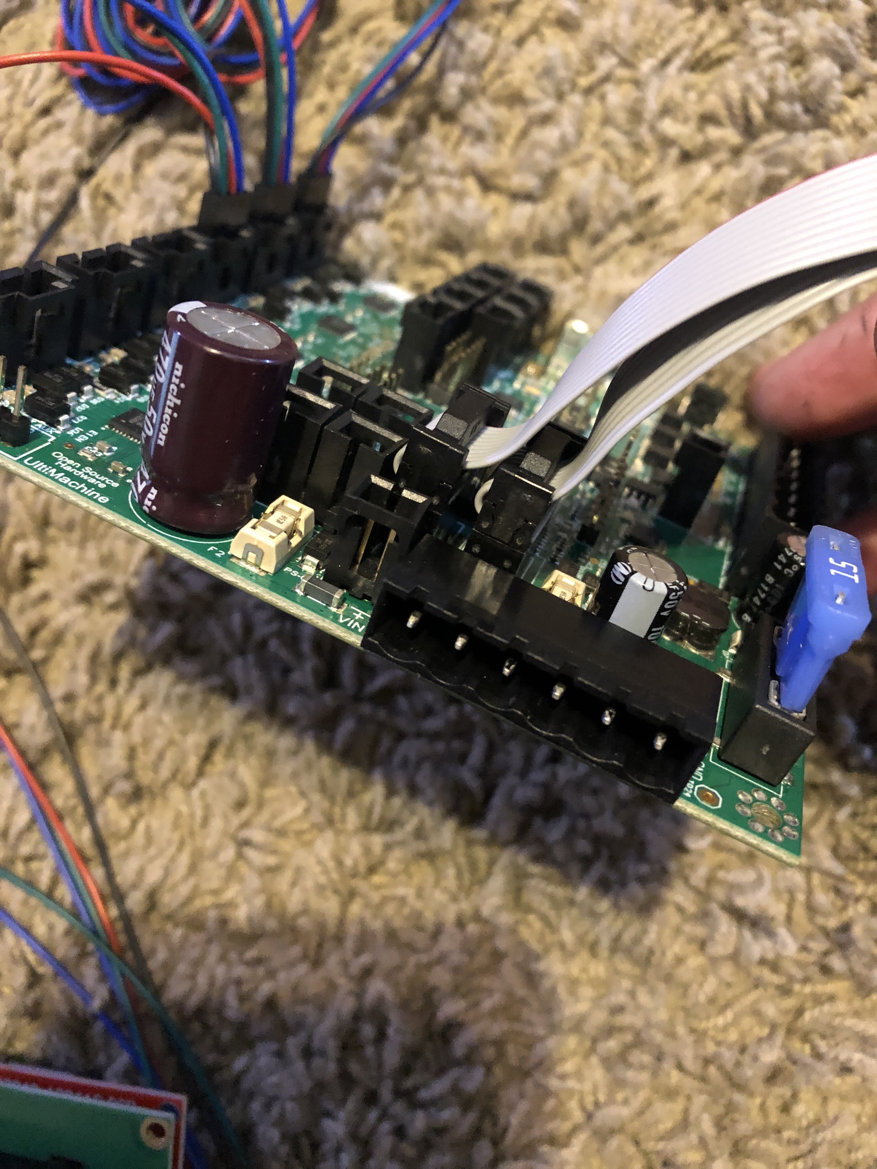
Now take a look at this picture from the page I linked above. The part with the screw terminals plugs into the board and is usually in a bag of parts. My parts package had one with four screws like this one, but also had one with six screws. Either will work, but if you use the one in the picture, it needs to be plugged in like it is in the picture. The red and white wires come from the power supply. If you use the connector in 1B, then the wires would come from that connector.
A pinout diagram for the board shows what you are powering:
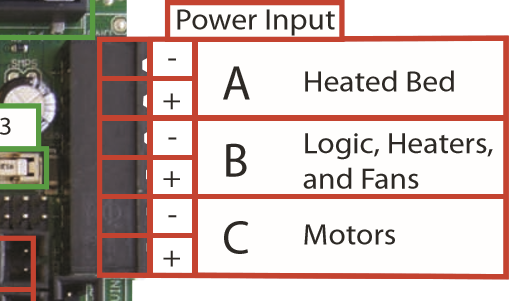
You are wiring up power for the logic circuit and the motors. You don’t care about the heated bed. Note the order of the inputs where the inputs run negative/positive/negative/positive/negative/positive.
If you look back at the picture with the loops of wire, you will see that the red wire (positive) comes in at the bottom, and the white (negative) wire from the power supply comes in just above it to the third screw terminal. Then you will see a loop of wire (mostly red) between the bottom screw terminal and the second screw terminal. And a second (black) loop of wire connects the third screw terminal to the first screw terminal.
So in summary, power is brought in to the motor screw connectors, then loops of wire are used to also connect the logic circuit to power.
Edit: The reason to cut off the connector like in 1A above is that we’ve seen problems posted to this forum that are traced back to a loose connection in the connector used in 1B.
1 Like
Awesome I really appreciate your time and also I did receive one of those little connectors that you showed but that was it. I bought the whole kit assuming I would get everything I needed but I guess I didn’t. I don’t have a little bag of parts for the control board or anything so could you maybe show a picture using that connector? Thanks again
In this picture is a variety of plug-in screw terminals outlined in yellow with a blue arrow showing where they plug in.
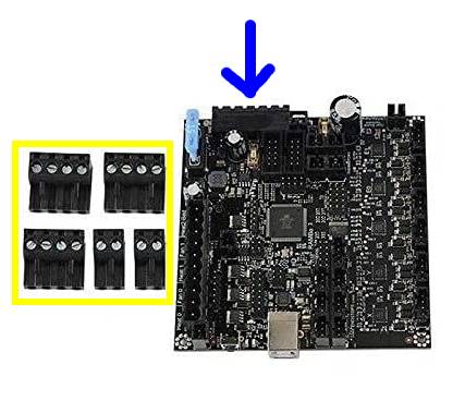
They come with the board from the manufacturer. They are not something Ryan adds to his kit. It is possible one of them is already plugged into the board when it shipped. If so, make sure it is plugged into Motors and Logic. As mentioned above, you don’t need to connect the heated bed terminals.
my bad I just found that little piece! I think I understand now thank you so much for your help!