looked at a bunch of the 3D printed ones but I don’t have a printer and finding both LCD+Rambo seemed to not be working, plus I thought I should probably add a fan? I already got a lot printed for free and kind of didn’t want to ask for more…
So I was thinking of getting one of those cheap ABS enclosures on amazon for the PCB’s / Probably mounting the LCD to the lid (card out the side) and the 1.4 board to the mounting board and adding a fan on one of the walls. Maybe something like this for e.g. https://www.amazon.com/AIRIC-Waterproof-Electrical-220x170x110mm-Electronics/dp/B09F934YG3
Just drilling holes for the cables Not sure how to keep dust out and allow cables in.
I figured the ones with the mounting plates would be easier?
Specs to look for in a fan?
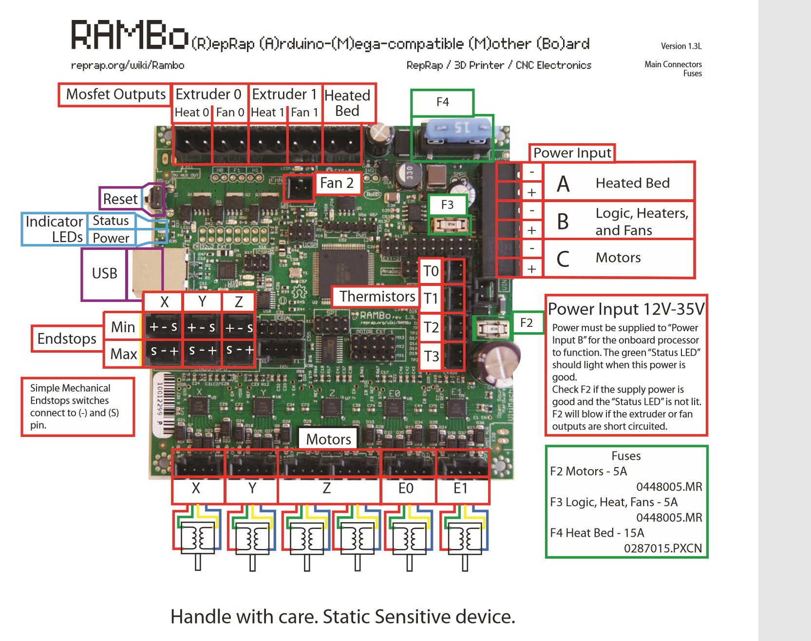
The wiki here: Rambo v1.4 - RepRap
is about all I can find nd says only:
“Extruders + fans and logic, 5A 12-35V (fuse can be exchanged for up to 10A capacity)”
Are those specs are even correct for the fans, when I look at amazon for the DC motors do I just look for:
For fans, assuming you are running your motors at 12V, get a 12V fan. I know the Fan3 works with the standard V1 firmware, and I think Fan1 and Fan2 do as well, but if you use any of these pin pairs directly, you will have to issue g-code to turn the fan on. I’m guessing you want the fan on all the time. The suggestion has been made by people on this forum that have more electrical/electronics experience than I have, the right solution is wiring the fans directly to input power. With this solution you don’t have to be too concerned about the amperage of the fan, and it will run any time you have power to the electronics.
As for enclosure, just about any plastic box will work. I’ve seen MPCNCs with electronics in plastic storage containers and plastic tackle boxes. But I am going to make an alternate suggestion…perhaps for the future. Why not design an enclosure and cut it out of wood (or acrylic) on your CNC? I don’t remember seeing a wooden enclosure on the forum, but it should work, and it would look cool. If you are new to using a CNC, there are some skills to be learned before you can tackle this kind of project.
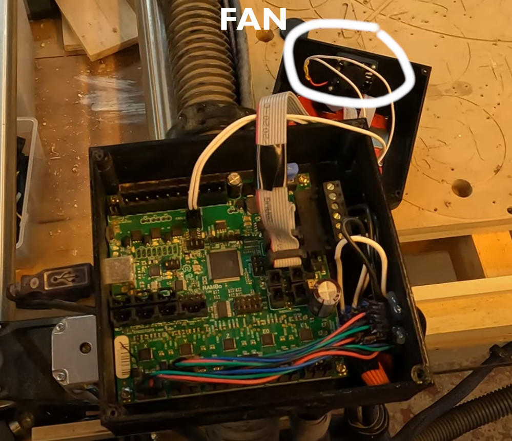
I’d been using the direct-to-power-supply setup for my fan since I first set up my LR2 but finally got up the nerve to do a proper fan setup.
Now my fan turns on when stepper motors are engaged and turns off 1 minute after the stepper motors turn off. It doesn’t change airflow but feels more like the way it’s supposed to work
Thanks Robert. I did think about designing in wood then I wasn’t sure about electronics and wood combo. Wood absorbs moisture (risk?) and also heat can burn. Then, I saw electrical conduit in ABS and somewhere read ABS is fire resistant (dubious claim?).
https://www.amazon.com/Raspberry-Cooling-Brushless-Cooler-Radiator/dp/B0831JM535/
These say Rated voltage 5V but the description says 3-5.5V, IN the right ballpark here?
I get confused on how to now Voltage vs Amp and do you look for more or less etc.e.g. if it is rated at 5V is less good or bad. I probably need to find a good DC electronics primer.
Thanks Darwin, Yeah that’s a great video; I plan on making a Z-probe at some point. I think will avoid firmware changes “for now”. Enough to learn but code doesn’t scare me though possibly poorly documented FW updates probably takes extra care and I think I like the “anytime the board is on the fan is running approach” but what do I know, I’m still learning.
I guess your fan is underneath the bottom and that is a 5x5 enclosure roughly? Couldn’t quite tell how that was mounted. Perhaps a pipe clamp and a longer rail (pipe) or somehow on that Corner part?
12V 6A. 120/220 with US cord, cords for other countries are not an option, but it is a standard connection and can be found locally.
…so you want 12V fans. The stepper voltage doesn’t really come into play anywhere. Your steppers are fed 12V, but that voltage is chopped by the stepper drivers, so the average voltage they receive is appropriate to the current desired.
I wasn’t sure about electronics and wood combo.
I’m just a hobbyist with electronics, but I have zero issues putting 12V electronics in a wood housing. It is something I’ve done for other projects, but not for my Primo electronics. I do put the electronics on standoffs of some sort, and it is not something I would do with MAINS (120AC) power. For wood, I use hot glue to build up a pad for each corner, then once hard, I will go back and install the electronics with a second pass of hot glue. Note that I’ve seen a lot of pictures of Primo builds, and some of them have their electronics mounted directly to the wood of the machine or to the table it rests on (there are probably standoffs).
Good plan. That’s exactly the route I went and given that I turn the machine and steppers on at the beginning and the steppers don’t shut off until I park the machine at the end it’s functionally the same. Part of the exercise was to try some small firmware changes before I moved on to the z-probe stuff.
The fan is attached to the top of the enclosure. It’s lying on the spoilboard in this photo:
If I were starting again I wouldn’t use this enclosure design.
It would be nice to detach the lcd, and on the lr2 there are designs that mount on the y plates.
tbh, For a while now I’ve used a laptop to connect to the cnc.js web interface which is running on a Raspberry Pi connected to the rambo board so I no longer use the lcd or the sdcard on the rambo.


