I was (and am) able to check by bearings. I use a pair of silicone tipped tweezers to see if I can rotate the bearings. If I can “easily” then they’re loose. If I can with “some resistance” they’re good. If that tool isn’t able to rotate them, then they’re too tight.
I realize that this is ambiguous. My intuition on this is borne from years of tinkering with mechanical things, like engines and other machines. There is a feel to a bearing that is properly loaded which is just not possible to measure well with a torque wrench, since the proper amount of friction is very low, but present. A bearing that is too loose will also have other slop, which causes problems with impact. One that is too tight will have too much friction and create more heat than you want.
The tolerances for the MPCNC are actually quite wide, because it’s low impact, and low speed.
To put it in more measurable terms the test mentioned fore the trucks also works for the core. If you tilt the gantry rail at 30°, the core should not roll at “free-fall” but rather roll at a more controlled pace. That is that it should reach it’s terminal velocity within about 12-18" of travel. (Terminal velocity in this case meaning that it should no longer accelerate.) This isn’t really a defined speed, because there is a fairly wide variation, depending on the surface finish of your rails, the stiffness of new bearings (Which are always stiffer when new) and the actual mass of your parts. There is some tolerance for a little overtightening, because the plastic will deform slightly over time.
In this case, I’d say that it means that the movement is smooth and not “sticky”. There should be little force needed to overcome static friction, and the bearings should not have “too much” tendency to come to a complete halt. I base this off of what bearings in other projects feel like. If you’ve built 3D printers, you should have some idea what well adjusted linear bearings feel like, and this is not dissimilar.
As per above. Too loose is if there’s isn’t enough drag on the motion, which will allow motion in the XY plane that will cause slop in the finished cut. Too tight is if the bearings bind and do not allow proper motion with the supplied amount of power. Motor power needed to overcome bearing friction reduces power available to move the router through the work.
This might mean that your prints are not dimensionally accurate. Maybe slicer settings. Hole compensation (Making holes bigger) will allow more movement of the axle bolts which will reduce overall bearing tension. A little underextrusion will do the same. There is some adjustment available, and as I said, the plastic WILL change over time. I’ve had to tighten my Primo a couple of times over the past year of operation.
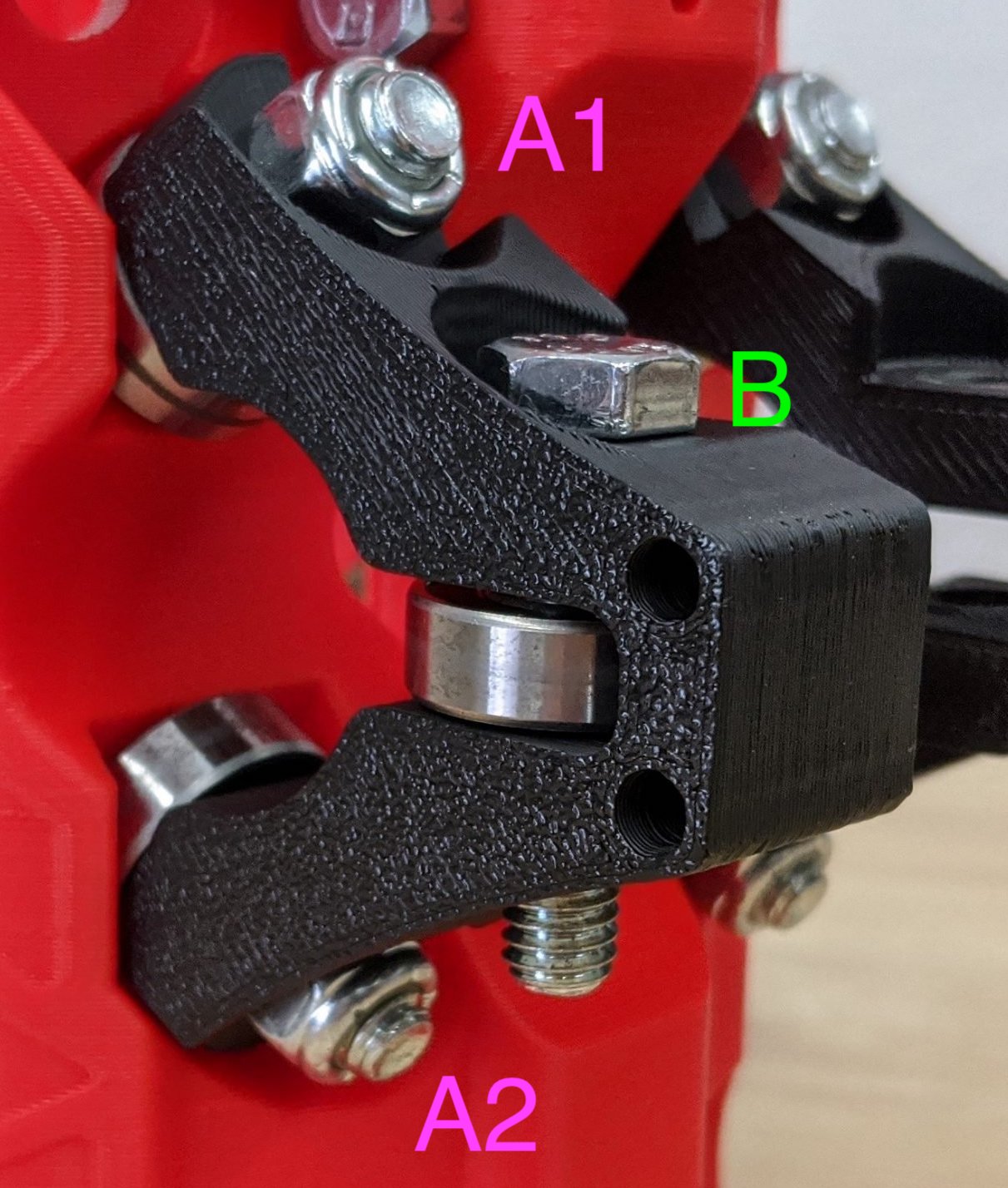
Some of the things that I’ve seen that indicate tightening is required:
- Nut/Bolt combinations turning with the bearings. The bolts should remain stationary. If they’re turning, then there’s friction where it shouldn’t be, and the rotational load is not being taken by the bearings, as it should be.
- Movement in the core relative to the XY plane. This indicates that the core bearings have some play between them and the gantry rails. This is sometimes seen as “chatter” in the bit, and sometimes as flex when cutting. A finishing pass that does not contact the work probably means that the bit was pulling inwards during the roughing pass.