Or do I need more wattage? if not what’s the recommended wattage? Thanks in advance.
ps: Also with regards to AWG cable, can I use 30 AWG instead of 26?
-Sebatian
Or do I need more wattage? if not what’s the recommended wattage? Thanks in advance.
ps: Also with regards to AWG cable, can I use 30 AWG instead of 26?
-Sebatian
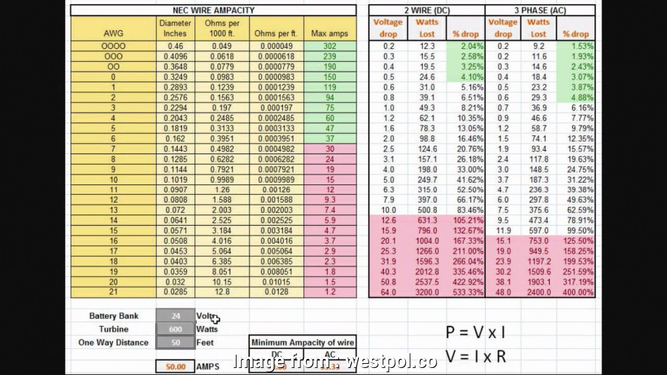
12V*5A=60W. So if is it really 30W, that is 2.5A. 5A is probably fine.
30ga for the motors? I don’t think so.
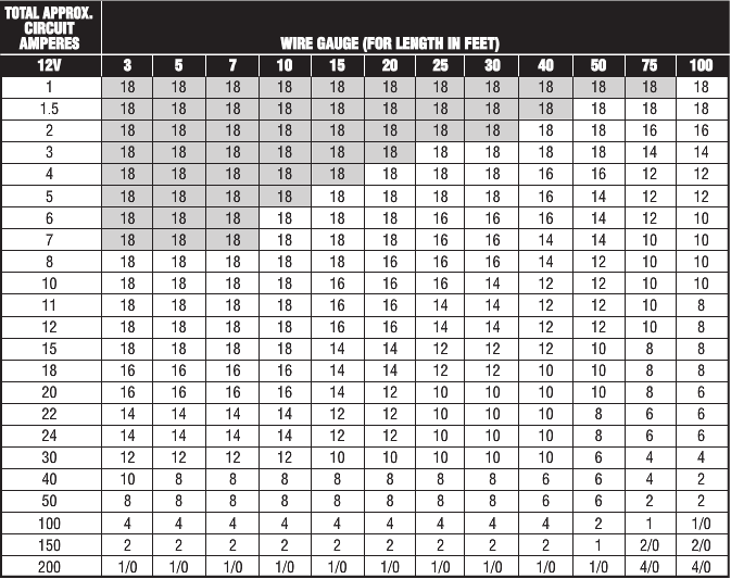
That char looks a bit off. What kind of wire is that for? Seems according to that chart even 20awg wouldn’t Cary enough current for a stepper.
The issue with both charts is that you are only running 2V to 4V to the steppers, not 12V or 24V listed for the chart. Rerun the chart at 3V and see what happens.
Not arguing with you… you are welcome to use whatever you wish. Have a great day!
i run my steppers at 19V 3 is minimum.
the issue i see is that these charts seem to be more for voltage drop than for current rating and neither specify what type of wire is being used. solid wire can carry more current than stranded, copper wire caries more than aluminum. and the max current rating is based largely on the insulation and the number of conductors you are running together in a bundle. none of that information is given.
its like listing a feed rate for you machine without listing DOC, RPM, bit type and material your cutting. i’m not saying they are wrong just that they don’t seem to apply to what stranded copper THHN insulated wire should be able to carry.
So this is something I’ve been confused about, so maybe you can help me. While the motors are typically powered by 12V and up, I cannot make the the numbers work out for the voltage to the steppers. It varies by stepper but let us take the ones Ryan is currently selling in his store: KL17H248-15-4A.
If I look up the spec for these motors, I get 2.8 ohms per coil, and in the V1 maintained firmware, the current is set 0.8A. To me that says (approximately and on average) that the stepper driver is delivering 2.24V to the stepper. I’ve looked up the specs for a few other steppers, and the resistance per coil varies, but at 1A of current, all were under 4.5V. Am I missing something?
And that leads to the follow-on question. I read a number of times that increasing the voltage to the steppers from 12 to 18 or 24 will result in a bit more torque at higher speeds. But if the steppers are already running so far below the max voltage of the power supply…
Stepper drivers provide a current source, rather than a voltage source. So when you set them to .8A it’s not about or average its providing .8A (at least as the steady state current. The same way your power supply provides 12v at 0-6A) the voltage will very to maintain that current.
What your numbers are missing is that your circuit is not resistive but inductive. So while the coil has a resistance of 2.8 ohms and a minimum voltage of around 2.24V That would be the holding voltage when the coils have been energized for a long time. During a stepping state the coils will resist the change in current because of the store magnetic energy. So the impedence will be much grater and the voltage to the coil will need to be greater to force the change to happen quicker.
If you understand how a capacitor charges and can take time to charge the capacitor based on the size of the capacitor and the voltage applied to it. The motor coils work in a similar way but while a capacitor is seen as being a short in the instant until charged at what point it is viewed as a break. An inductor is viewed the opposite (as a break when power is first applied and a short at steady state.)
Does that explain it?
The voltage going to the motors is 12V (for a 12V supply, and the wires will take some off). But it isn’t on all the time. They might be on for 20%, which would average 2.4V. When the steppers move more quickly, they make effectively a reverse voltage, which means only 6V might be reaching the motors, which would make them be on for 40%, which is still 2.4V average.