Roger that… I will swap out my black terminals with green ground the dc-.
I was not planning to daisy-chain anything, other than using the clips that come with the terminals. Makes sense regarding noise path and induction. It’s also not ideal for the added resistance. In my work (home construction), resistance of series connections can often cause problems. NEC allows daisy chaining through outlet tabs, push connectors, etc, which have much higher resistance vs wire nuts and pigtails. I have some air compressors that will trip breakers if plugged in away from the panel on a circuit that was wired this way. So I always use pigtails in homes… and “start to end” wires on my DIY stuff.
Good thought adding a snubber on AC coils! Using mostly DC coils my entire life, I totally forgot about that. I have an assortment of safety snubbers from a previous project that may work; got several values to try on an arduino/relay/inductive motor project, which had random logic errors caused by spikes when the motor switched off at the wrong part of the sine wave.
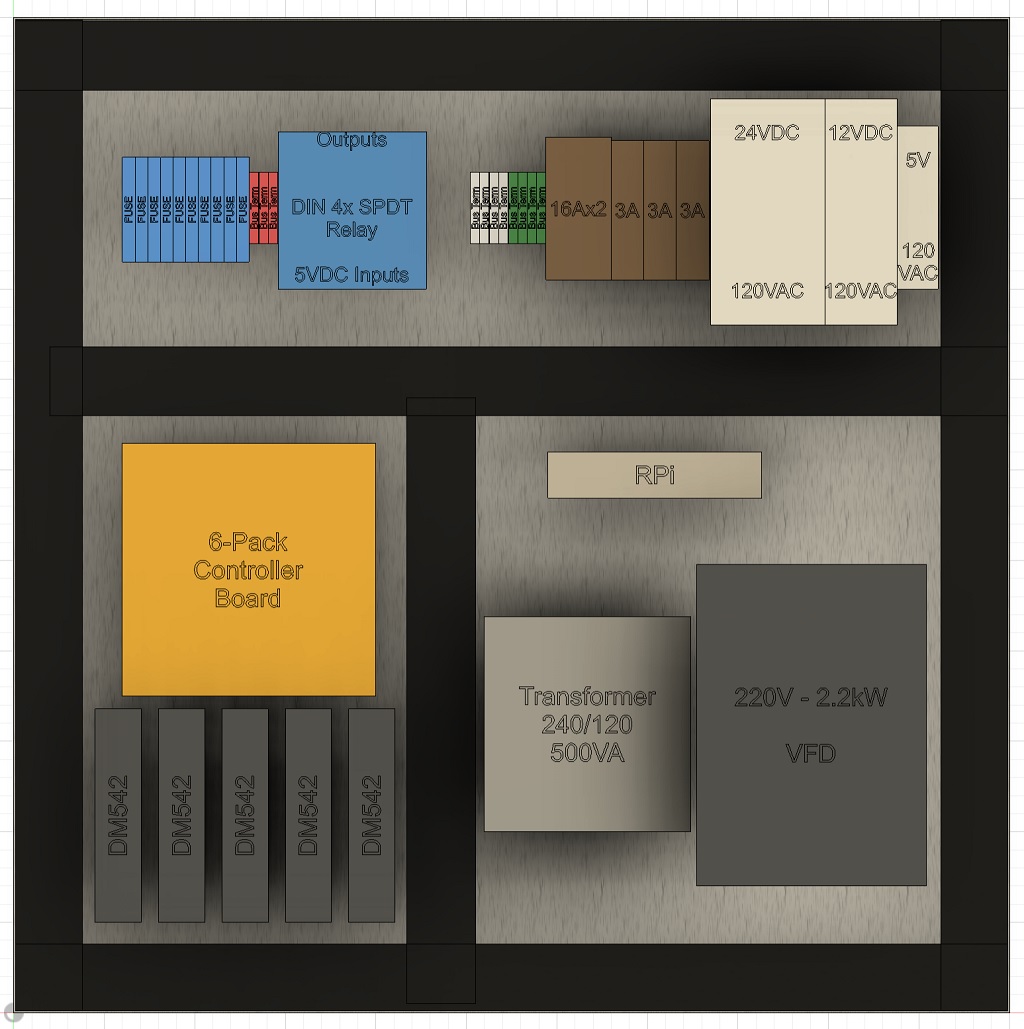
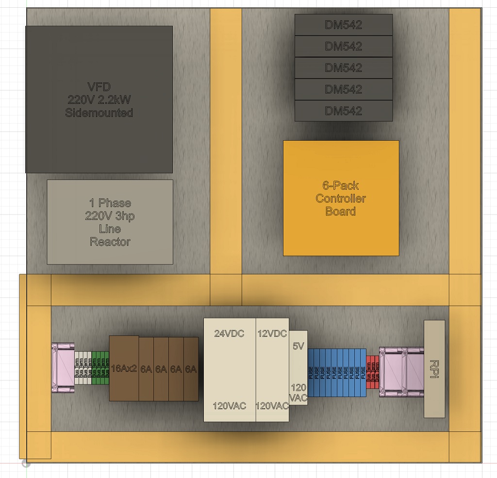
Also, adding that VFD contactor may not be a big deal with the latest changes to my plan (and yeah 24v is fine… much easier to find). I had more discussions with my industrial buddy, and came to the conclusions that I really just need to use 2 boxes, including a 24x24. So here is what I have now using 24x24x8 and 16x16x8:
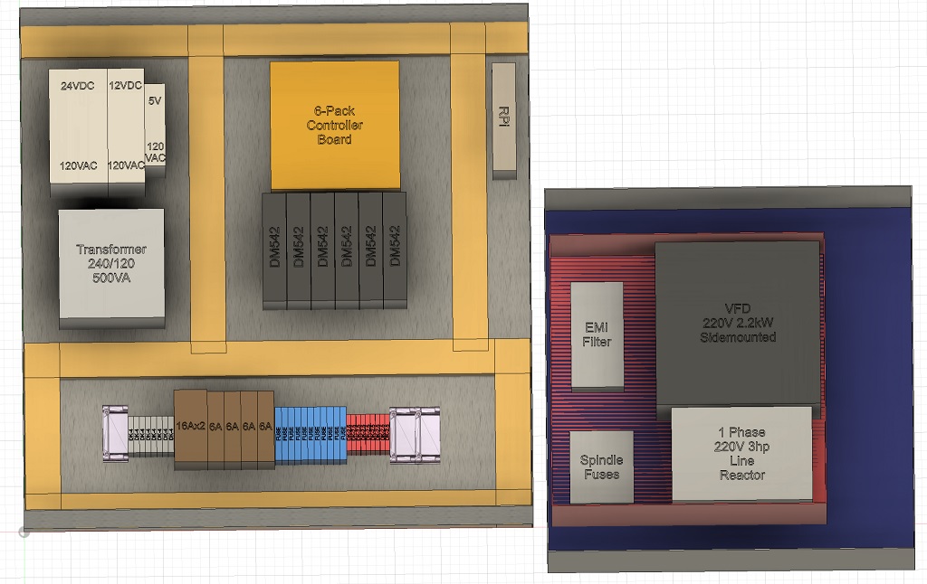
Note that’s a 3-phase output filter, not 1ph line reactor. Also the transformer won’t be there as I’m using 4-wire. This obviously gives a clean layout that is easy to work on and upgrade. Note I included 2 options for the VFD box, red is 12x12 and blue is 16x16. Only $25 more for a 16x16, but saving space would be nice if you think 12x12 is OK there (I will properly address airflow to vfd in either case).
I did have some what I feel were silly arguments with my buddy over placement of parts on this. He said breakers and fuses should always go on top left away from other stuff, and only terminals for wire entry (or devices that wire direct like spindle fuses) should be on bottom. When I worked out wiring for this, I just didn’t like all the extra length of wire, and even worse having signals parallel to power for longer than necessary.
I get that the average joe industrial operator may expect fuses in a certain spot, but for myself I always follow power wires in and go from there. So breakers on bottom next to HV terminals seemed logical. Also, my layout makes it easy to keep signals and power separated better. I also like that (for me anyways), there is an obvious separation between hazardous areas and safe areas. Having breakers and fuses together would mean HV hazard changing fuses.
What are your thoughts on this?