I just built a lowrider cnc… got everything together powered on, repetier host on. Ran into a couple problems… Only one Y and one Z sorry motor will move (more like makes a loud clunking noise) sometimes it moves sometimes it don’t. The z axis feels like it is snagged up but when powered off moves freely. I’m using a skr pro 1.2… The steppers are nema 17 1.5amp 67oz… on the tft screen, the screen functions but I can’t move the axis or anything. Can someone please tell me what to do. I’m not good with flashing, software, and all that so I can’t give much info on what I’ve done but followed the directions on this site.
Welcome @J_Gorby !
Congratulations on getting this far into your build. Friend of mine has had MPCNC parts sitting in a box for 2yrs.
Able to share picture of your machine and controller board? Would like to understand how wiring is connected, and driver slots used, jumpers and such.
For snagged Z movement, during my initial assembly I needed to fix alignment of linear rails when I noticed them binding. Also, they need occasional cleaning and lubricating to avoid steppers skipping. The steppers skipping making a loud clunking noise is mechanically harmless, they’re not getting hurt/damaged. Consider 84oz steppers Nema 17 84OZ/in Steppers – V1 Engineering Inc.
The motors look like they want to move but don’t… If I move y forward they will just clunk clunk and jerk forward just the slightest bit where u can see it… It’s every axis… I did get the firmware figured out and now have all the steppers working they just ain’t working right. I can take pics later tonight
Do you have the LCD Motion screen set to 0.1mm?
I did that and had similar results to what you described (noise, seems like it is trying to move), then realized that 0.1 mm is too small to see anything happening. When I changed the screen settings to 1mm, I could detect the movement.
Don’t set it to 10 mm, or itmay cause damage if one of the steppers is wired backwards.
It was set at 1mm… I checked everything the only thing I can think at this point is either the steppers are wired differently then usual or I may not have a big enough power supply? It’s a 12v 5a supply
Hmmm, OK, next step - when you make a 1 mm movement, does the display show that the position has changed?
Before turning on the power, I set the core in the middle of the gantry, set the gantry in the middle of the rails, and lifted the gantry an inch or so above the bottom, in order to ensure that it could move freely in any direction. When you power it up, the display should show X=0, Y=0 and Z=0. Any move command should change those readings. If the display changes 1 mm but you can’t see the movement, try 3 or 4 mm. If still no movement in either direction, then there are problems, but at least you (and we) have some additional information to go on.
Speaking of additional information, where did you buy your controller and other parts? If you bought everything from Ryan at V1E, then it will already be flashed properly, otherwise you will have to flash the proper firmware into the controller. There is a documented process to do so, and people here are happy to help you through it.
As mentioned above, pictures of your controller and LCD wiring will also help with diagnosis.
I think I figured it out. The wiring of the steppers are different to the board
Welcome to the forum! Glad you seem to have figured it out!
I got the steppers working I had to switch a couple wires around on the stepper motor wiring but now everything is working but the z1 axis…once plugged in and moved in 1mms itll make a clunk noise and on the screen it says driver malfunction please reset device or something along them lines. I put z motor in y1 and it worked it seems to be something on the board or the z stepper driver. I’m personally fed up with skr so I ordered a ramps 1.4 setup which will be here tomm. Hopefully that solves problem. I just want to get up and running. Has anyone done any engravings or inlays with this machine? I do have engraved coffee tables and it would be awesome if this machine was capable of such task.
IMO the RAMPS is a big step down, but still supported and simple. Back to the mini screwdriver to set driver current, and the 8 bit processor. Should work OK though.
For the Z1 on the SKR Pro, there are the 2 motor sockets. They are in series, so one needs the jumpers over the motor coil pairs. Not havjng them will have the TMC driver detecting an open circuit and theowing an error.
The SKR doesnt (usually) cause more errors, bit it detects more errors. (The end stop trigger issue was a bit of a doozy on the SKR boards though…)
Do u have a diagram for these jumpers
I followed the steps on the directions but the mpcnc and the lowrider cnc having 6 and 5 got me alil confused as to I ain’t bet good with the whole electronics thing
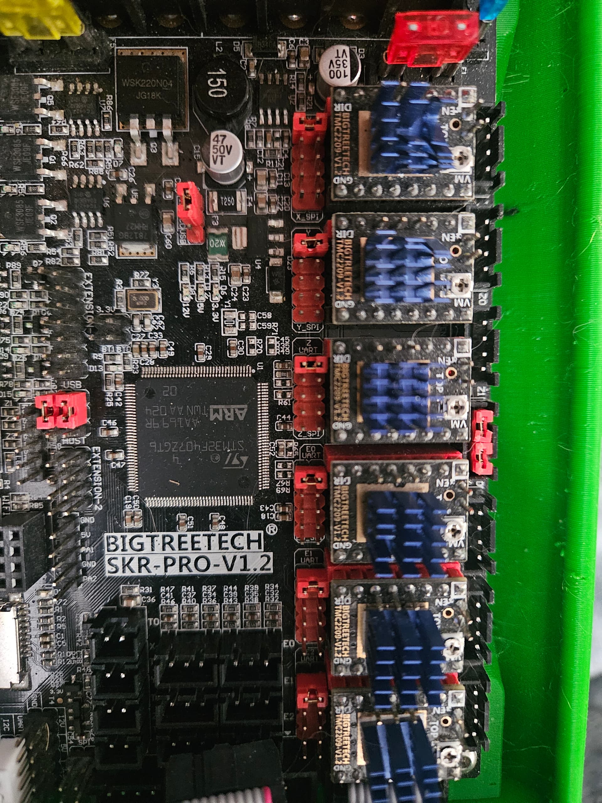
How about a picture? The 2 red jumpers on the motor connection on the side. Without those, the other Z motor (directly above it) cannot work, as it will be like having an “off” switch in the motor wires.
There are 6 stepper drivers on the SKR Pro.
From the top (as oriented in my picture) for the LowRider, they are X, Y1, Z1, (jumpered), Y2, Z2, and unused. (Do not put jumpers on the last one!)
Also take notice of the jumper blocks to the left of the stepper drivers. The SKR Pro comes with these blocks populated opposite. Onneach of these there should be one jumper across the top pair, and the rest of the block should be open.
Hope this helps…
Yea I have no driver on the last one but I have it junped
But other then that last stepper not being there and having it jumped, everything looks the same
How about a video? Hope something in here helps.
https://www.zoomtube.com/@azab2c/make/v1e-lr3?v=3_0&t=17_44_16
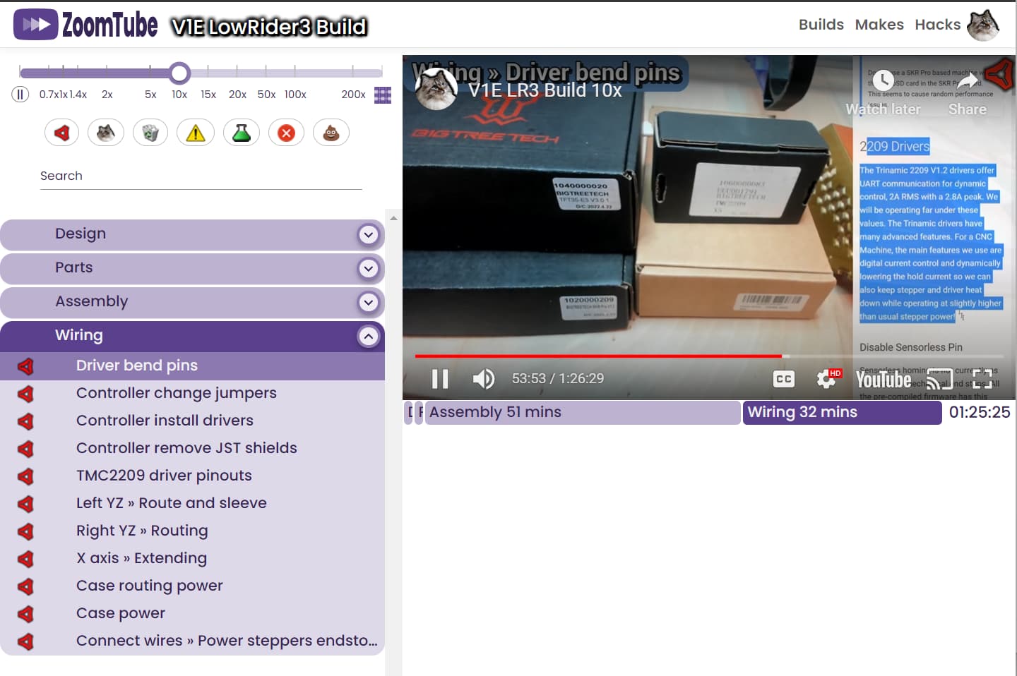
Early stage work, but sharing incase it’s helpful. Can play 2.5x to 200x, haven’t uploaded 1x playback content yet (25GB video…).
did you fold over/cut the sensorless homing pins as the documentation notes?
Hey guys I figured out the problem… The stepper motor wires was wired wrong and the wires was shorted out causing the motors to act funny. I removed the plastic holding the pins together and carefully soldered the wires to the appropriate pins on the board. All acts as should now and I know 100% I won’t get a bad connection again especially during a cut… Thank God I didn’t have to swap out for the ramps 1.4 kit like I was going to do. Thank you for all your help I greatly appreciate everyone who helped me along this. Hopefully today I get it all put together and possibly a cut. I ordered metal xy plates from v1 that would be here today and eventually I want to cut it some metal yz plates, or atleast MDF for I don’t feel the yz plates 3d printed at 70 percent feel like they will be strong enough for the long haul. What I like about this set up is you can start small like I did, 18*36 cut area and if u want to go bigger later on all u got to do is get some more conduit and print a few more braces and rail guides. Had anyone done any inlays or 3d carving with this machine?
3 Likes