When you’re measuring, don’t just measure the inside, either. I had an issue with holes being small, and tabs being big, even when I had the 'correct" diameter set for my mill. It turned out that the 1/8" mill (3.175mm) was actually making 3mm cuts, and setting the diameter to 3mm in Estlcam ended up with correct sizes both internal and external.
1 Like
I will look at modifying the end mill diameter. It is currently set to .25 and is .2485. While this may help a little it still would not account for one set of holes fitting and another not. I did however have my bits set in inches and designed the spoil board in mm but I’m pretty confident that Vectric would convert everything over as needed. I plan on making a few changes tonight and running some test cuts. I’m going to decrease my feed rates, decrease the step over and tighten my belts. It is possible there is flex some place in the system and I’m just trying to cut to fast causing the inaccuracies in my cut.
I think I may make the same cut 3-4 times with ever decreasing feed and step overs and see if accuracy improves.
1 Like
HI, i only mention this just for the sake of completeness, but have you checked the cut direction on your cam is the same for each hole? I find Climb cuts tend to undercut compared to the same machine and config when cutting Conventionaly. Your number differances remind me of the values i was getting when testing out my Primo which turned out to be cut direction.
Definatley support checking the Bit Diameter, one of the 1st errors i made. I also had to use a value slightly smaller dimension to get consistant inside and outside dimentions. Fully agree you should be getting consistant hole sizes.
Richard’s idea is worth checking out. That could definitely result in different size holes.
Bottom line, if you run a conservative finish pass there should be little to no forced flexing.
I gave this more thought… Belt flex error may not be constant, but the sum of error in the plus and minus directions should be more or less constant if you think about it (same total length regardless of position). Therefore hole size error due to belt variance across xy should result in same size holes… albeit theoretically in an hourglass shaped square rather than a perfect square… but all same diameter holes.
Otoh, one thing that I can see would 100% cause this is flex in the pipes. Pipe flex will be symmetrical in plus and minus, and the sum of plus and minus error will be larger at the center, and smallest at the sides. Unfortunately the only fix there would be stiffer tubes. This is why I had no hesitations when I got 1/8” wall Dom steel for my sorta large primo (24x24x6). If you really need the precision and are using thinner wall Dom, swapping in thicker tubes would help. If it’s a conduit version, unfortunately you’d have to reprint almost everything to upgrade.
I know there are different schools of thought regarding pipe thickness and weight for steppers to handle… but I think 1/8 Dom works well for a stock mpcnc. The only concern for steppers on a primo is the z really, and using a 1-start leadscrew can easily lift a very heavy 2hp water cooled spindle and my thick z tubes. Since z tubes don’t flex much anyways, you could use lighter there without sacrificing much precision.
I’m using 1” Dom with 1/16th wall and all
My side rails have additional support with little to no flex at all in them. While it would be a pain in the ass I could change to a thicker Dom on the tubes that the center piece rides on. I’m going to try a few things tonight and see what kind of results I get.
I’m not looking for machinest level accuracy but I would like to be able to put in a size hole to pocket out and get at least close enough to where I could slightly increase it and have the item I designed fit and not have to increase it by small amounts a million times and have all the holes be consistently off by the same amount. As it sits right now if I increase the size of every hole by .05 mm I will have some that fit nice with others being very loose.
As far as a finishing path I have been taking off .03mm to try and sneak up on an actual size that works. So if a finishing pass would have solved the issue one of the 10 .03mm passes I have done would have fixed it on the first try.
I’m using 1/2” pvc for pins and according to Home Depot the OD should be 21.33mm but of course you can not trust it to be perfectly round or that size so I checked with the calipers and turned the pipe and got 21.53mm I believe at its widest point so I started off at 21.55mm for a super snug fit and they didn’t even come close so I kept on going back and increasing the size by .03 to sneak up on a perfect fit and I’m currently at 21.69mm and up the Y axis I’m a bit loose and really snug along the X axis.
I designed some L brackets that once locked into the spoil board have an inside corner of exactly 50x50 from my home position so I can stick a piece back in and be consistent every time.
0.03mm (aka one thou where I live) is pretty hard to achieve on any printed Cnc. Even on a Bridgeport it takes some practice to regularly get parts to a thou. It sounds like you know what to expect and how to go about milling generally. I am curious to see how you go about this and what your results are.
I am finishing up on a sorta extensive upgrade myself. Cf petg parts here and there, h2o vfd, properly built controller box, 24v steppers, better bearings (vs $0.25 popcorn bearings) and probably more before I seal the lid back on. I may get 0.05mm tolerance when it’s all done… not that I really need it. I just want cleaner aluminum top surfaces really.
Lots of different opinions here.
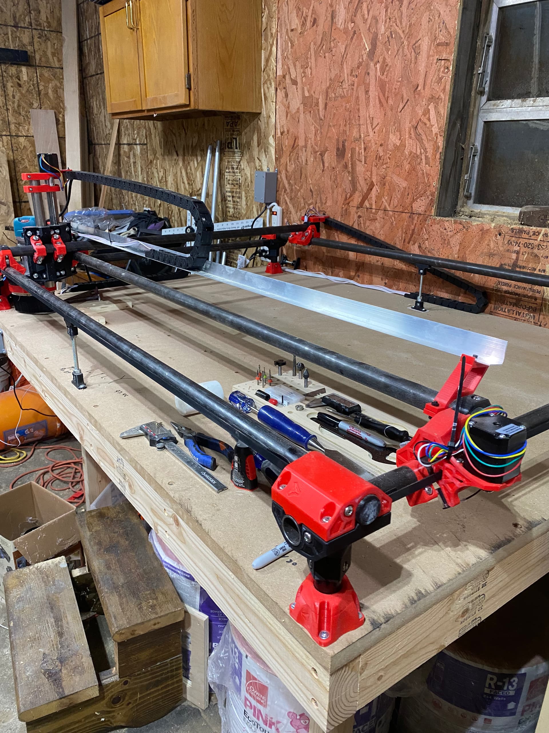
No pictures of your build so it is all guesses.
You should absolutely be getting repeatable results. Error or no repeatability is a must. My advice would be post your machine and way more details.
33mm/s at how deep? That is VERY fast for trying to get super accuracy. How many flutes, depth of cut…and a full depth finishing pass is absolutely necessary. (3D printed mill, need to have a spring pass).
Try a single flute upcut, 10mm/s 4mm DOC, .5mm full depth finishing pass and lets see what you actual numbers are. From there, faster or deeper and see when the numbers start to break down. You are coming at it from the too fast side (you are running at the suggested rapids speed, not milling speed). This is all a guess without knowing how your machine is built.
2 Likes
Where I live it is a thou as well but because the machine uses mm I try and stick to that when making something like a spoil board so when I make a jig I can know that the particular location is 50mm x 50mm and always get back to that spot easy enough. I am able to increase the size gradually by .03 mm and not only hear it take it off but see the slightest amount come off as well. So it is pretty accurate to be able to take off so little for a printed cnc.
I originally went with petg and while it was strong it was not stiff enough. This iteration that I actually completed I used PLA pro by Polymaker I believe. It has the stiffness of Pla and the strength of petg with a higher melt point and better layer adhesion. I also printed with an extra wall.
I’m really only doing wood and may try some aluminum at some point if I can get it to make a hole the size I tell it to. My plan is to try and make a few custom products and make a few bucks on the side In Order to buy a more robust machine. I will probably stick to a DIY machine like the queen bee and not so
Something like the one finity. Starting off with name plates for my wife’s office with the NY State Troopers seal. Still working out some kinks before I start making them for sale.

I blacked out the last name and department but this was my trial run.
1 Like
I have my build posted other places but here is what some of my sizes are
I have a 29x46 work area with mid span supports. The supports have virtually taken out any kind of flex out of the side rails. I’m using 1” DOM tubing with a 1/16 wall.
I can definitely take the speeds down and plan to give that a try tonight by doing multiple holes and decreasing the feed rate by 10% for each hole starting at 70 inches per minute and try a conventional cut like somebody suggested. Maybe just do a 70, 60, 50 and 40 with a finishing pass and change my bit size to the .2485 I measured it to be. My depth of pass I use a maximum of bit width/2 unless the recommended depth is less based on the manufacturer. I’m strictly using white side bits and the V1 bit set.
The entire build is very square and after homing and moving it out a given amount and measuring how far each block is out they are the same to within the thickness of the mark on my tape. I have also put in a v bit sunk it into plywood by 1mm raised it and moved 80mm and sunk it again and got a measurement of 80.02 mm so probably spot on and within the margin of error for me measuring and my calipers.
I have tried multiple bits. Almost all are 2 flutes like the bits and bits 425-DNC125LR 1/8 diameter 2 flutes 1/16th depth of cut.
Also tried a few compression bits and regular 1/4” upcut bits.
I will try an additional full depth finishing pass as well and see what I get from that.

They don’t do anything for the cross beams.
I highly suggest you do it like I said. Start at 8-10mm/s and work up. Why bother making 10 cuts if you do not get what you want at 8-10mm/s? We need a base line to work from. (sorry I work in mm/s as in/minute are hard for me to visualize.) in/min to mm/s - Google Search so start at 20in/minute. If you can;t get a perfect cut with 3-4mmDOC and a fill depth finishing pass of 0.5mm then there are larger issues at play.
70…is pretty far from there.
So you are making a ton of 0.1" passes and no finishing full depth pass? Please have a look at the milling basics page. Try 3-4mm DOC single flute upcut.
A single flute is highly recommended. If you are going to use a 2 flute slow your RPM all the way down.
1 Like
When working in wood with a extremly high RPM router a single flute stands a chance of clearing a chip before it comes back around. A two flute has a much smaller flute channel and comes around twice as fast. So you will recut a lot of chips, higher load, and burn more often from the double contact.
I will try your recommendations and see what happens. I have been running my router at 12,000 -14,000 and can slow it down to 10,000
Ok so here is what I did.
- I snugged up the belts slightly
- I adjusted my end mill size to .247”
- I reduced my rpm down to 10-11k
- I adjusted my feed rate to 24 in/pm (10 mm/pm)
- I adjusted my depth of cut to be .157” per pass
- I changed my cut to a conventional cut instead of a climb cut
- I then duplicated that pocket 15.9mm at a feed rate of 36,48 and 60.
I cut them and found the holes to be to small by .1 mm. So I made the hole bigger by .1 and recalculated and ran the passes again. The 24,36 and 48 while snug all fit and if I was to increase by .2 mm to allow for the initial size issue and a little wiggle room I think I will be good. However the 60 was to small and would not fit. So I think 48 in/pm might be my sweet spot. There was no difference in fit between the 24 and 48 in/pm cuts. I didn’t figure out how to do the finishing pass in Vectric until after doing these tests. So tomorrow I will add the same bit into the pocket and put in a .5 mm pocket allowance for the first cut and 0 for the second cut and reduce the passes down to 1 and see what I get.
The important thing is all 3 of the first holes fit the same and I can make allowances for .1mm in my pockets.
I will try this again with the full depth final pass tomorrow and make a series of holes to see if they all stay consistent and then report back with my findings. I will also allow for .2mm extra in diameter. It is possible .15 will be enough.
1 Like
My plan is to do 6 holes up the Y axis and 6 along the x axis at 48 in/pm with a .5mm full depth finishing pass and see if all holes along both the x and y are the same. I will also be increasing the size of the holes from the actual measurement by .2 mm.
The full depth finishing pass should absolutely clean things up. I actually like Climb cutting, cleaner in wood for me, but that is another good thing to test. When you get other setting you like.
Instead of going faster, try to increase your depth of cut. If a cut takes you 4 steps down, doing it in 2 is literally twice as fast. Most wood can be done in 1-2 passes. The machine gets weaker the faster you move it. Although with a two flute endmill you will not be able to go as deep per pass as a single flute.
I’m going to keep my eye out for single flute end mills. I’m currently using white side bits that are Astro coated by bits and bits and I do not see any single flute bits other than their low helix bits for foam. I can more than handle running everything at 48 in/pm. I’m not really conserved about time as much as accuracy. My wife has some inlays she would like me to do at some point where accuracy is more important than speed. I will eventually get the kinks fully worked out. This is all new to me and there is only so much info you can absorb before you just need to do it and work it out for yourself.
Thanks for the work you put into this design.
The other thing about deeper cutting and the finishing pass is using more of your endmill. If you cut everything in steps of .157" thetip of the bit will get dull and leave the rest of the endmill unused. I used to get 45 minutes of cutting out of the cheaper single flutes I used, now I get 10+ hours I would guess.
There are two different single flutes in the v1 shop. Carbide Single Flute Long – V1 Engineering Inc and 1/8" Single Flute Carbide Endmill – V1 Engineering Inc
Excellent discussion regarding tuning for feed/speeds/etc. Sounds like you’re at the final points of the tuning process now. I haven’t got around to ordering any 1-flute yet; no good reason other than my 2 flute collection is lasting longer than expected. I plan on ordering some from Ryan, but I also plan on giving one of these a shot just for aluminum work:
LMT Onsrund seems to get good reviews, and they are made in USA. I assume it would have higher quality carbide and sharpening compared to cheapo bits, given the price/branding/reviews. They make all kinds of high end 1-flutes; not sure the one I linked is the best for what I want lol. What attracts me to it is the shorter flute length. MPCNC are not stiff enough to use a larger DOC on alum anyways, so the short flutes are perfect for alum on a primo.
edit: Hey, I also have some whiteside bits… they’re excellent for an mid-upper tier bit. I also have used Spetool carbide… pretty good for the price. I stick to throw away bits under 1/8" though… break too easy to invest in quality lol.
I have been sticking to mostly 1/4 bits and the one mistake I had where the bit slipped down and everything went all to hell really quick was not damaged one bit. So instead of snapping a bunch of 1/8 bits I stick with the 1/4 for a bit more meat pocketing and bigger areas unless the hole is smaller like it was when I made my bit and tool holder.
I think I may have finally worked most of it out thanks to Ryan last night and will work on seeing what DOC I can push per his recommendations along with some single flute end mills and stick with bits and bits for the specialty carving and bowl bits they have.
Yeah it is so, not, straight forward as you can see. Reading things and suggestions from all sorts of perspectives, different machines and companies. You really have to test things methodically. Find what works for you and move to the next step. I only revisit settings typically with each revision or when someone figures something new out and posts it here.
Here, everyone started off assuming it was a machine/hardware issue when it was much more of a CAM issue. You never know though.
When we were beta testing the LR3 I think all of us realized we were not pushing any of our machines very hard…or maybe not using them correctly depending on how you want to word that. So many factors come into play. For me, when something works reliably, I stop messing with it so I can keep working on other things. Saving a few minutes of a robots time typically is not worth it to me.
Another cool example is nesting, https://deepnest.io/, that program is insane and works so well to save material, but the time it takes to make the CAM after the fact is not always worth it. I can make a single setup in estlcam and just pattern it and go, cuts my CAM time by a factor of twelve when making 12 parts. (my LR3 side plates). Nesting is great when you have a bunch of different parts to fit in a board but not always time efficient when you have a bunch of the same part.
1 Like