Probe LED Always On - LR4/Jackpot Issue

Hi,

Since this morning, I’ve been having trouble with my LR4/Jackpot.

When I freshly boot my CNC, I can home all axes without any issues, but I’m unable to probe the Z-axis. I keep getting the following alarm:

<Idle|MPos:23.000,23.000,-17.000|FS:0,0|Pn:P>
G91
G38.2 Z-107 F200
ok
G90
[MSG:INFO: ALARM: Probe Fail Initial]
ALARM:4
G10 L20 P0 Z0.5
G0 Z25
<Idle|MPos:23.000,23.000,-17.000|FS:0,0|Pn:P>
ok
error:9
[MSG:ERR: GCode cannot be executed in lock or alarm state]

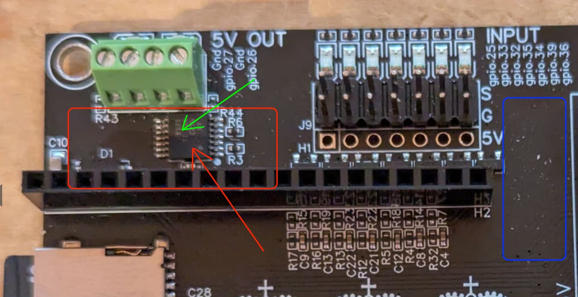
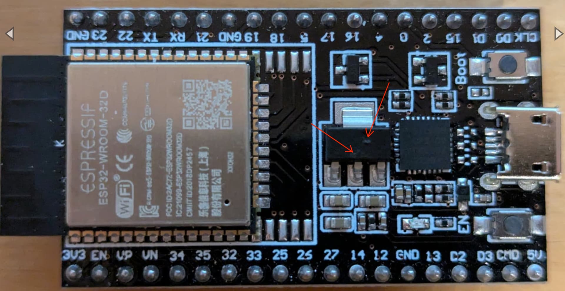
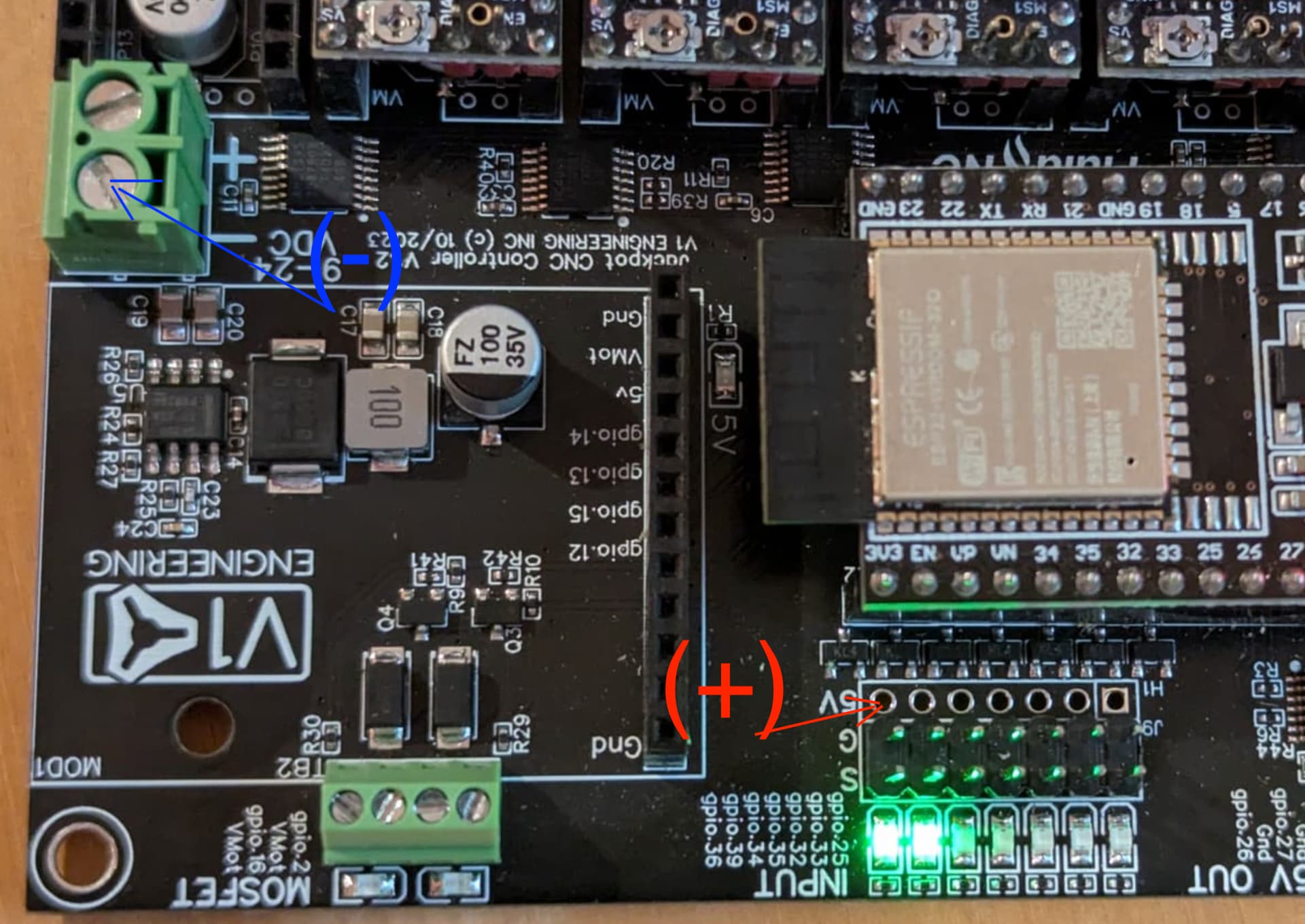
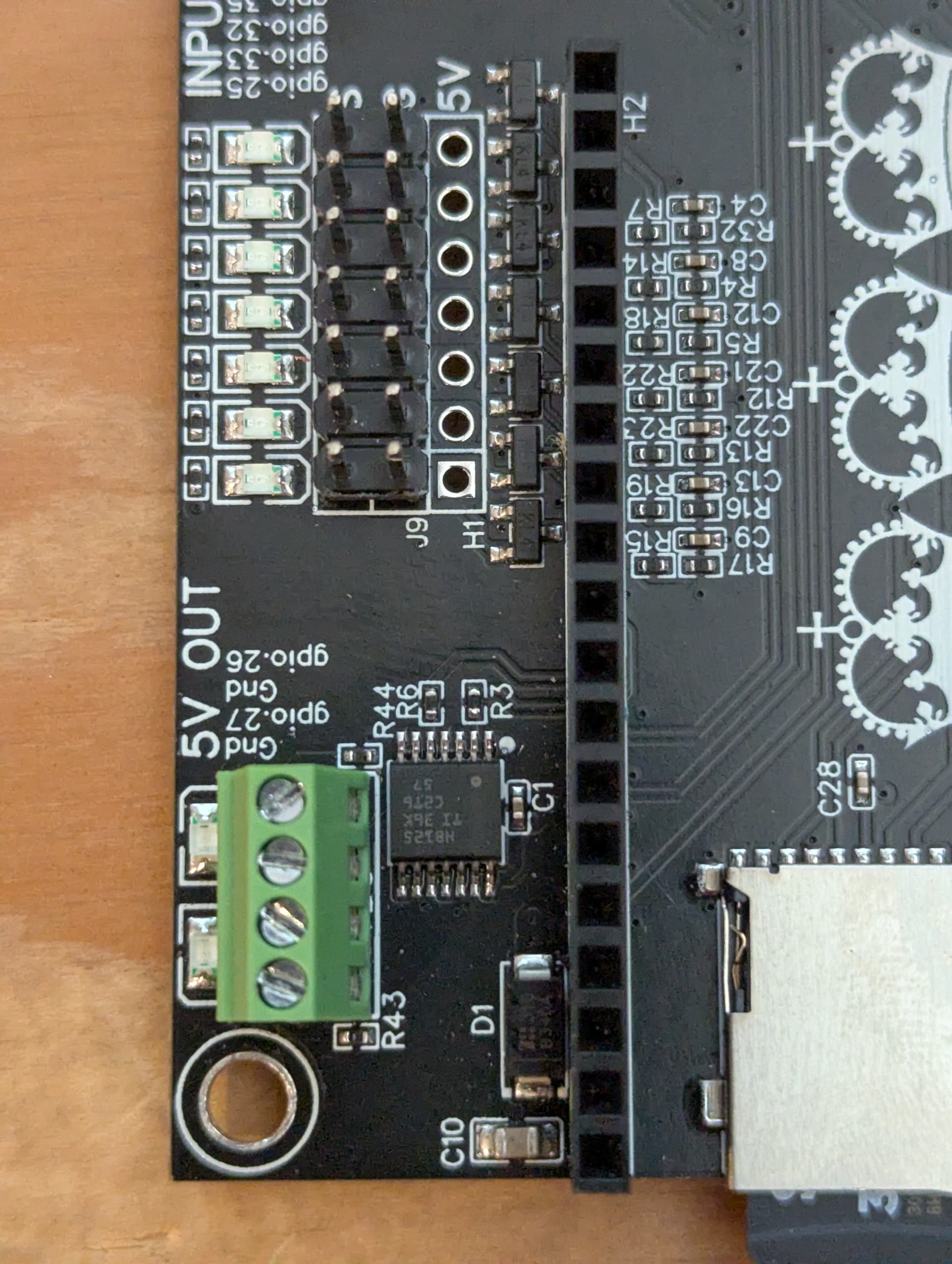
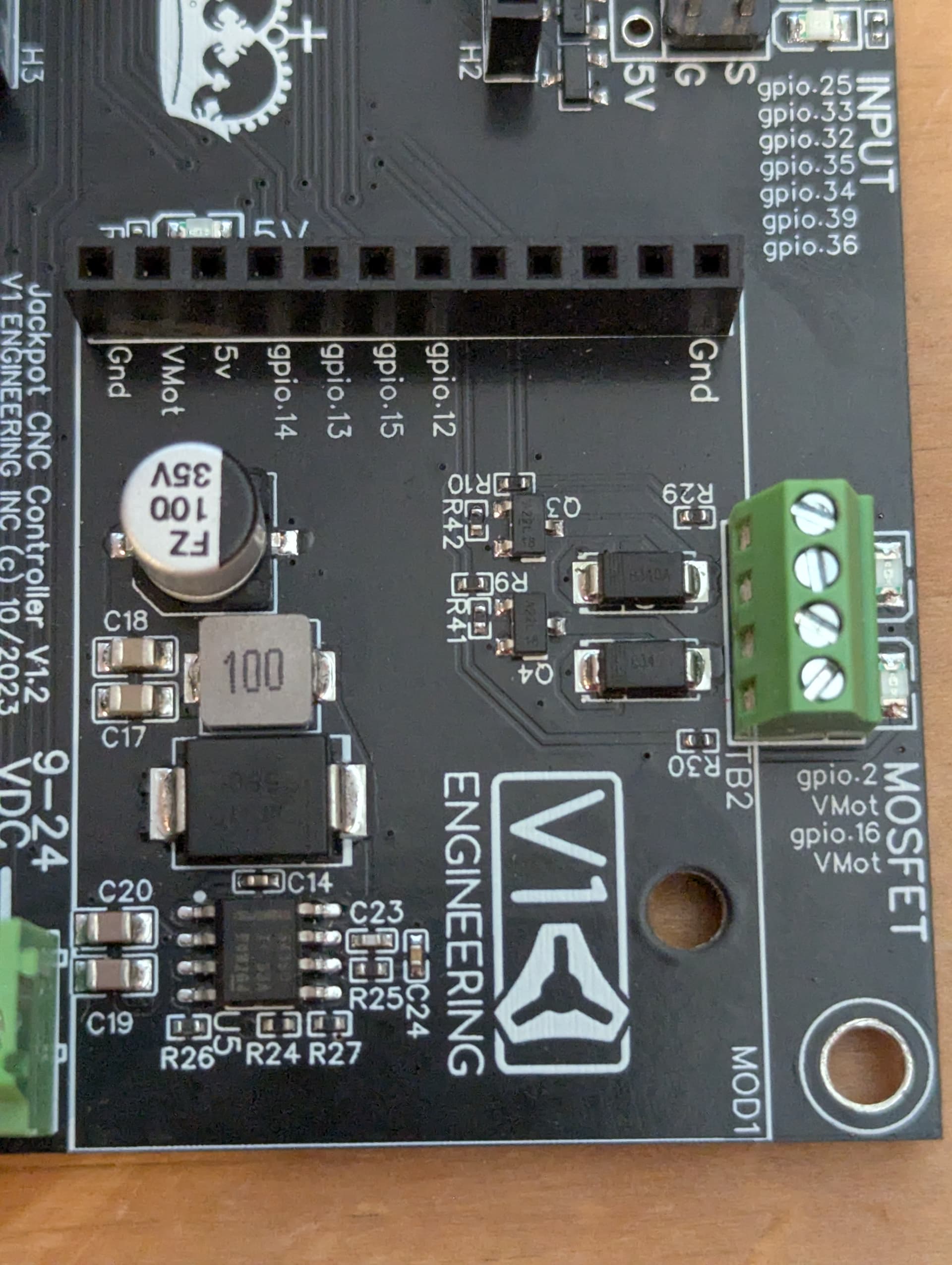
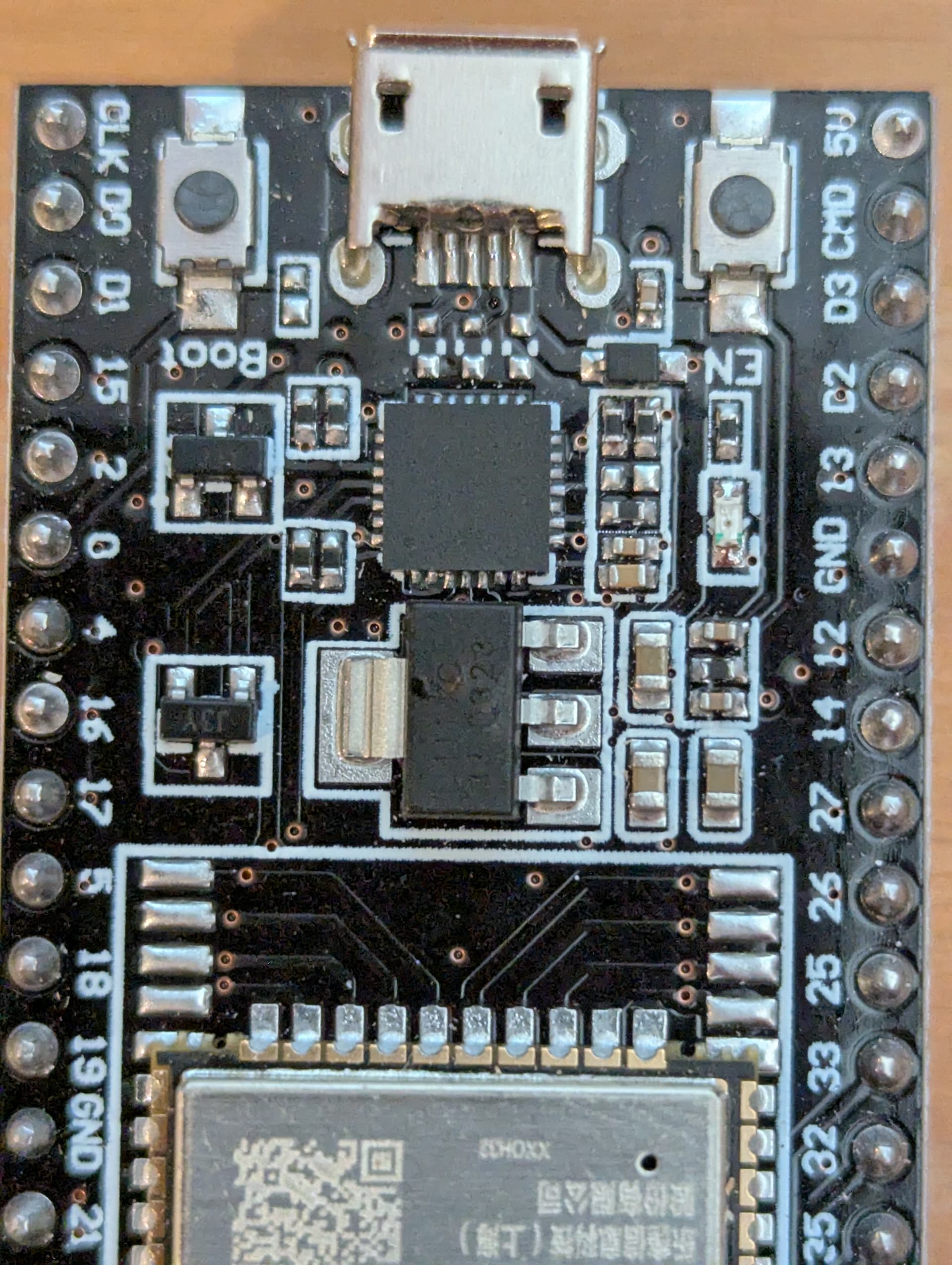
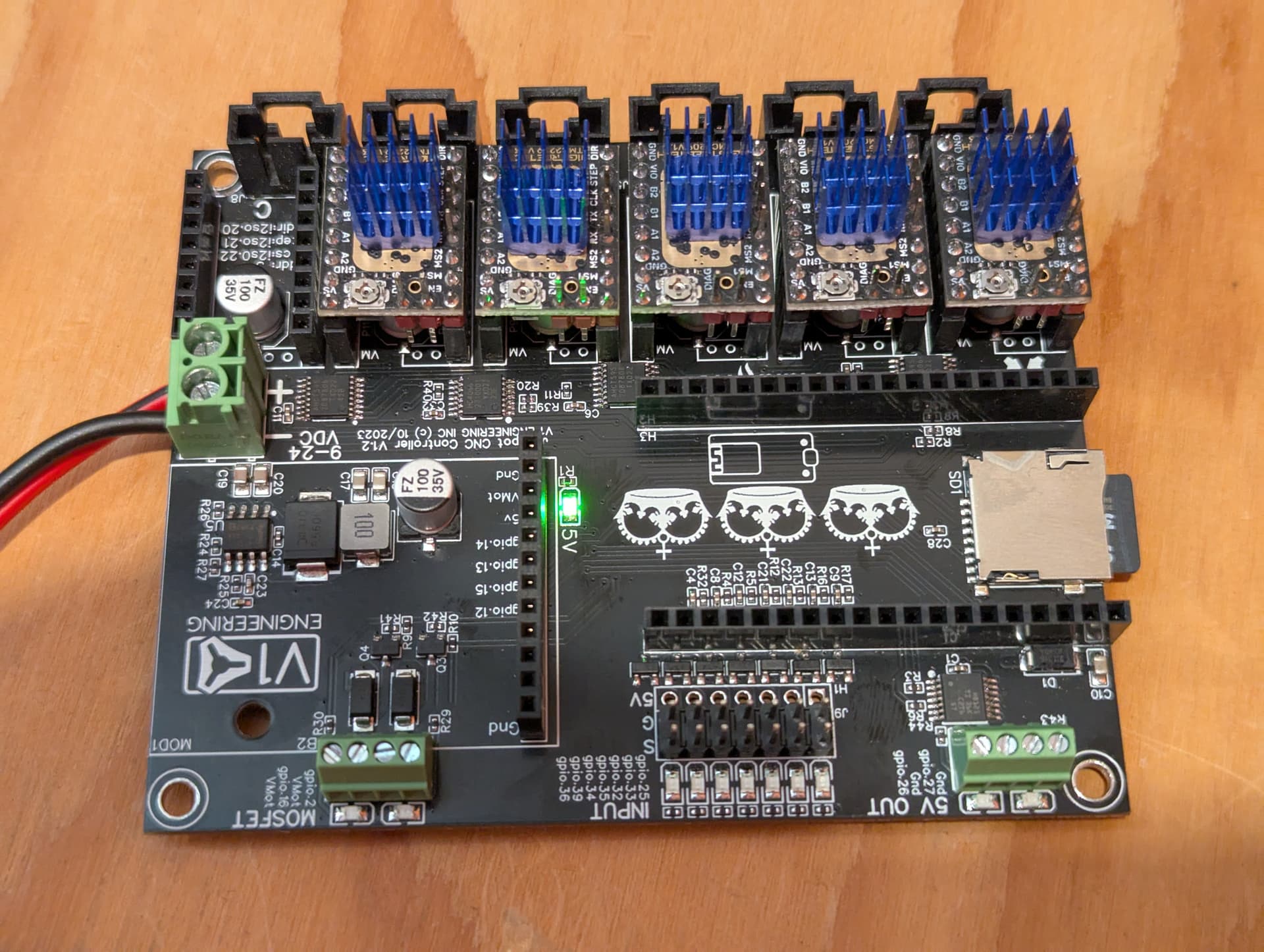
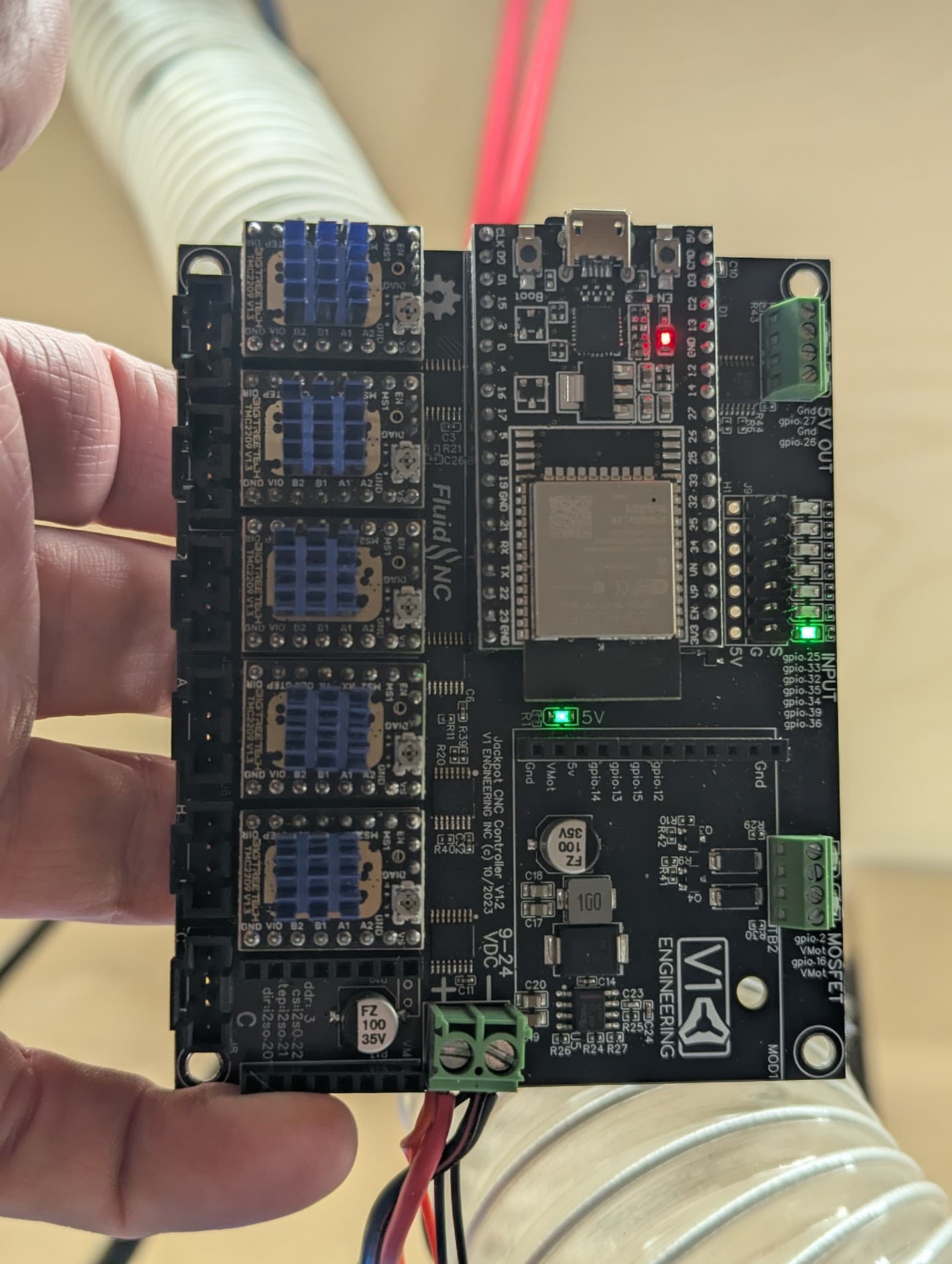
After some research and troubleshooting, I realized that the probe LED on my Jackpot is always on. Even after unplugging all the wires, the LED remains lit! The only way to turn it off is to remove the ESP32 completely—otherwise, it stays on, like this:

I tried installing the latest firmware as a fresh install, but it didn’t change anything.

Of course, all these wire manipulations were done with the controller powered off.

Do you have any other ideas I could try to fix this?

Thanks!

Are you using the appropriate config.yaml file from here?
FluidNC_Configs/LowRider CNC at main · V1EngineeringInc/FluidNC_Configs

I know that probe pin is configured low (connection is NO) while the endstops are configured high (connection is NC) so the probe LED indicator is typically backwards of the endstop LEDs. What happens if you trigger the probe? Is it staying lit regardless of probe contact?

Someone also reported an issue recently where they opened the WebUI while the Jackpot was still initializing and it caused some strange behavior with the Z axis. Is it still a problem when you restart the Jackpot and wait 15-30 seconds for it to initialize?

Yes, I’m using the config.yaml file from the official repo. So I supposed the probe pin are correctly configured. And early this morning the problem was not there. All was working correctly.

When I’m trying to trig the probe, nothing change with the led. I have removed my probe connector and carefully tried with a screw driver directly on the pins to be sure it’s not my probe the problem. No change…

I also have wait more than a minute before openning the webui. That change nothing. I’m not surprised because the led are lit as soon as I powered up the board.

After booting up, what is the output of entering the “$SS” command in the terminal? That’s usually where most debugging starts with FluidNC.

If that doesn’t provide any useful information, my only other thought at the moment is to try changing the config to use the next pin over in case there is something wrong with that GPIO. So, change the probe config to use GPIO 39 instead of 36.

In config.yaml, it’s defined in this section:

probe:
  pin: gpio.36:low
  toolsetter_pin: NO_PIN
  check_mode_start: true

The $SS ouput doesn’t show any unusual details…

$SS output:

[MSG:INFO: FluidNC v3.9.4 GitHub - bdring/FluidNC: The next generation of motion control firmware]
[MSG:INFO: Compiled with ESP32 SDK:v4.4.7-dirty]
[MSG:INFO: Local filesystem type is littlefs]
[MSG:INFO: Configuration file:config.yaml]
[MSG:INFO: Machine LowRider]
[MSG:INFO: Board Jackpot TMC2209]
[MSG:INFO: UART1 Tx:gpio.0 Rx:gpio.4 RTS:NO_PIN Baud:115200]
[MSG:INFO: I2SO BCK:gpio.22 WS:gpio.17 DATA:gpio.21Min Pulse:2us]
[MSG:INFO: SPI SCK:gpio.18 MOSI:gpio.23 MISO:gpio.19]
[MSG:INFO: SD Card cs_pin:gpio.5 detect:NO_PIN freq:20000000]
[MSG:INFO: Stepping:I2S_STATIC Pulse:2us Dsbl Delay:0us Dir Delay:1us Idle Delay:255ms]
[MSG:INFO: User Digital Output: 0 on Pin:gpio.26]
[MSG:INFO: User Digital Output: 1 on Pin:gpio.27]
[MSG:INFO: Axis count 3]
[MSG:INFO: Axis X (3.000,1078.000)]
[MSG:INFO: Motor0]
[MSG:INFO: tmc_2209 UART1 Addr:0 CS:NO_PIN Step:I2SO.2 Dir:I2SO.1 Disable:I2SO.0 R:0.110]
[MSG:INFO: X Neg Limit gpio.25]
[MSG:INFO: Axis Y (3.000,683.000)]
[MSG:INFO: Motor0]
[MSG:INFO: tmc_2209 UART1 Addr:1 CS:NO_PIN Step:I2SO.5 Dir:I2SO.4 Disable:I2SO.7 R:0.110]
[MSG:INFO: Y Neg Limit gpio.33]
[MSG:INFO: Motor1]
[MSG:INFO: tmc_2209 UART1 Addr:3 CS:I2SO.14 Step:I2SO.13 Dir:I2SO.12 Disable:I2SO.15 R:0.110]
[MSG:INFO: Y2 Neg Limit gpio.35]
[MSG:INFO: Axis Z (-97.000,3.000)]
[MSG:INFO: Motor0]
[MSG:INFO: tmc_2209 UART1 Addr:2 CS:NO_PIN Step:I2SO.10 Dir:I2SO.9 Disable:I2SO.8 R:0.110]
[MSG:INFO: Z Pos Limit gpio.32]
[MSG:INFO: Motor1]
[MSG:INFO: tmc_2209 UART1 Addr:3 CS:I2SO.19 Step:I2SO.18 Dir:I2SO.17 Disable:I2SO.16 R:0.110]
[MSG:INFO: Z2 Pos Limit gpio.34]
[MSG:INFO: X Axis driver test passed]
[MSG:INFO: Y Axis driver test passed]
[MSG:INFO: Y2 Axis driver test passed]
[MSG:INFO: Z Axis driver test passed]
[MSG:INFO: Z2 Axis driver test passed]
[MSG:INFO: Kinematic system: Cartesian]
[MSG:INFO: Connecting to STA SSID:XXXXXXXX]
[MSG:INFO: Connecting.]
[MSG:INFO: Connecting…]
[MSG:INFO: Connected - IP is 192.168.x.xxx]
[MSG:INFO: WiFi on]
[MSG:INFO: Start mDNS with hostname:http://fluidnc.local/]
[MSG:INFO: HTTP started on port 80]
[MSG:INFO: Telnet started on port 23]
[MSG:INFO: Flood coolant gpio.2]
[MSG:INFO: Mist coolant gpio.16]
[MSG:INFO: Probe gpio.36:low]
ok

So I have tried with the GPIO 39… And that’s working… It seems there something wrong with the GPIO 36… I hope there’s nothing other… :worried:

For now, that’s fixed… :smirk:

Thanks for your help!!!

1 Like

You have messed with your firmware and are using an untested version.

Interesting, that is fine. We have a spare for a reason. I actually check every single board for this exact thing before it leaves. Not sure how this could happen after the fact but your little diode is probably messed up. I have had a couple show up that way but replacing it takes a hot air station.

Yep… I know… I realized while making the post that I had forgotten to change the version in the FluidNC Web Installer… But I can confirm that the issue started before changing the version. At that time, it was either 3.9.1 or the previous one that had been tested. I’ll revert to 3.9.1 during my next work on my LR!

That’s fine. The alternative works for me. I just hope nothing else is broken. Time will tell.

1 Like

Well… Obviously… It could only be that, or at least something just as trivial…

Today, I reinstalled firmware 3.9.1. I ran a job that lasted about 3 hours. It worked perfectly.

Once it was done, I turned everything off. Later in the day, I wanted to start another job… And then… Boom! Same issue on the backup pin!!!

I turned everything off. I disconnected everything (limit switches, steppers, only leaving the 24V power wires connected), hoping it would help. Turned it back on… Same behavior. Turned it off. Removed the ESP-32. Turned it on. Only the 5V LED lit up. Turned it off. Put the ESP-32 back in, being very careful to insert it in the right direction and into the correct pins. Turned it on… And then… A beautiful white smoke rising from the ESP-32…

I’m discouraged! In your opinion… Would it be worth trying to find an ESP-32 nearby? Or is it a lost cause, and I need a whole new Jackpot??

That’s a really weird set of symptoms.

That means the GPIO pin on the ESP-32 was likely blown.

Can you post high-resoluntion pictures of the ESP-32 as-is (removed from the jackpot) and high-resolution pictures of the jackpot itself?

Something is very wrong to be blowing IO that way.

Yes, you can find suitable ESP-32s locally.
What part of the world are you in?

We need to figure out what is blowing your electronics up.
Do you have a DMM to troubleshoot with?


In this little video, you can see the boot process and the fact that the 2 green leds (the 2 blowed up pins) are flashing.

Eastern Canada.

Yes, I have one. A basic one, but I have one. :slight_smile:

The upper picture has some double exposure.

What’s going on here? Note the appearance of the IC… I think this is shadow, can you confirm?

What are the flecks on the board, shown as an example in the blue box?

The voltage regulator on the ESP-32 looks cooked to me. I’m surprised it even turns on. Was this where it smoked?

Can you make the following measurments and report what you see?

Measure the voltage on your power supply, with it not attached to the jackpot.

Shut down the power supply, remove the ESP-32 from the jackpot.
Install the PS wiring (Only) to the Jakpot
Power up the power supply.
Measure the voltage at the VMOT inlet connector (where the PS is installed)
Measure between the (-) input to the jackpot to the 5V rail.

I bet we can find a suitable ESP-32 on Amazon.ca

I thinks it’ ok.

I think it’s just dust. I don’t see anything with the naked eye, and there’s none visible in this photo (taken this morning after wiping this section with a cloth).

I think it was in this area. But it happened so quickly that I’m not 100% sure. When the smoke and noise started, I quickly turned it off.

Sure! For the first test, I did this in my office with a different power supply (12V). It’s easier than doing it in the workshop through the rest of the machine.

12.30v

12.29v

It took a long time to get a stable voltage! For several seconds (10-15), the voltage fluctuated between 4.3 and 5.04. It eventually settled at 5.04…

I noticed two more things…

First, when I power on the board, the two LEDs next to the text “5V OUT” don’t light up. I realized this because while taking my measurements, they sometimes turned on and off…

Also, should the ones next to the text “MOSFET” be lit as well?

Finally… I think I found something major! The VMOT inlet connector isn’t solid! Not just the green part, but also the pins underneath! It looks like it’s not properly soldered!
Google Photos

Could this explain everything? The voltage regulator on the ESP-32, the unstable voltage on the 5V pins, the LEDs that don’t always light up, and especially the two probe pins that burned out (GPIO 36 & GPIO 39)?

At this point, I assume I need a new Jackpot & ESP-32… But I’d like to make sure this isn’t caused by multiple issues. If everything makes sense to you, that works for me. Otherwise, what else should I check/test before connecting a new controller?

1 Like

No question the solder of the power inlet connector is broken and looks like it wasn’t properly flowed.

That’s not good, an intermittent/bad solder joint will mean very intermittent power rail and can cause a number of bad issues including arcing at the connector.

Did you source your jackpot from the V1 store or from elecrow?
How old is it?

If it were me, I’d re-flow the solder to the green power inlet terminal block and see if the behavior improves. Given the number of different symptoms and inconsistent 5V power rail behavior on this board I’d say you have maybe a 50/50 chance of fixing the jackpot that way, depending on how stressed the components on the board were from inlet power problems.

I’m sure the ESP-32 has at least a damaged 3V3 regulator, so no question in my mind you need a new ESP-32.

@vicious1 - take a look through the last few posts in this thread…

1 Like

So that power socket does that when it gets overtightened. The next version of the boards will not use screw terminals here. These terminals need very very little force to completely hold a wire.

I use and power up all the boards before they leave, so that was solid when it left. If you tap it with a soldering iron it will be fine.

More concerning is how you keep popping inputs.

What are you using for a spindle? Some spindles are known to have lots of stray current. If you touch probe is feeding back from a funky spindle that is the issue here. We have never had a board lose an input before. You have to over power the protection diode.

A replacement esp 32 will let us know if the input diodes are cooked or not. But I have been following along and with your second input popping that is a giant red flag to say your touch plate is touching power somewhere. Bad spindle or static from the dust hose?

1 Like

The elecrow boards say elecrow in the silkscreen by the power input. This one is direct from me.

V1. Order #23734. December 9, 2023

I’m almost certain that the problem came from the wire putting pressure on the connector inside my enclosure. My enclosure is a custom version of the official one. I made it wider, added a switch and a connector, but the depth is the same as the original.

Makita RT0701C.

Here is my setup.
The probe wire enters and exits through the core using the standard path.

Then, it runs through the wire sleeve (purchased from V1) and follows the dust collection hose along with the router’s wire.


Then, it enters the controller enclosure and connects there.


Possibly an important detail: The power supply also provides power for a 24V fan and an LED strip to illuminate the work surface.

Finally, my dust collection system consists of a vacuum and a cyclone separator.


The next question is going to be is your vacuum hose grounded?

1 Like

Looking a lot more likely at this point.

Definitely, I never thought that this could generate static and potentially damage the board… But when you think about it, it makes perfect sense. Especially since I just realized that even the vacuum doesn’t have a ground…

In your opinion, would wrapping a bare wire around the vacuum hose from the LR4 to my cyclone and connecting it to the ground of a power outlet be sufficient?

That coil in your hose should actually be metal, diggin out some of that at one end and grounding it should be a good enough ground.

If you ever touch that cyclone right after milling you will feel how much builds up, I am down right scared of mine. My hose is grounded but not my bucket, that thing packs a punch some days.