I’ve had this idea in my head for awhile and you know, I should definitely start something new instead of finishing old stuff.
I’ve never flattened my spoilboard and I’m not really sure I plan to. I would like to know where the high and low spots are. My table just sits on saw horses so it might make sense for me to shim it a bit.
I have no intentions of trying to accommodate an unlevel spoilboard with gcode modifications or anything like that. I would like to make a FluidNC extension or something for visualizing it and auto-probing the bed.
The part that kept me from going down the software side is that I’m not going to crawl over my table to probe a bunch of spots. I want to connect a probe that can do that on its own. There are those 3D probes but I don’t want to do that. I want to use my existing probe setup without having to disconnect anything. Plus, my spoilboard has cut marks all over so probing a tiny point would be misleading.
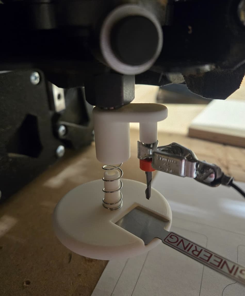
So, here is my current prototype. I haven’t actually tested it yet. It’s cold out there.
Currently, it requires 2 3D printed parts, 1 spring, 2 old 1/8" endmills, and the tiny touchplate.
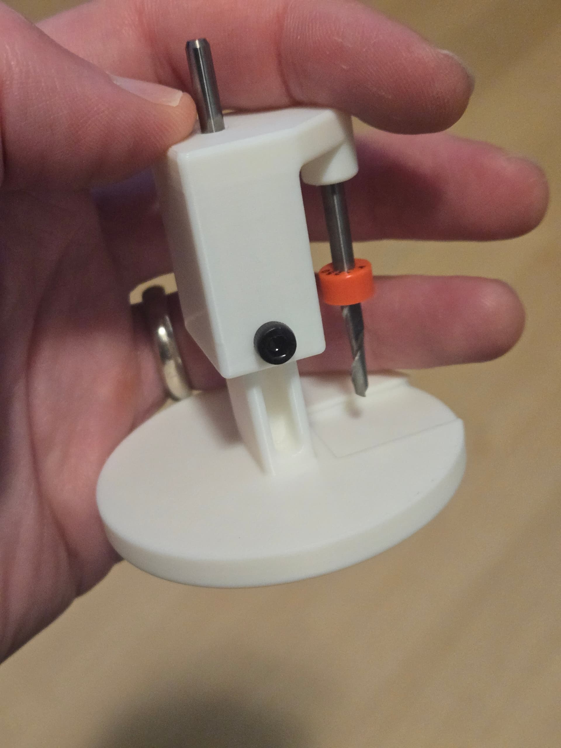
One endmill goes in the top to connect to the collet. Another goes in the spot off to the side. The tiny touchplate slides into the base. The spring connects the 2 3D printed parts.
I need to adjust the length of the 3D printed parts to help keep it straight and maybe get a different length spring, but it seems like it will conceptually work.
And actually, it could perhaps be modified to incorporate a 3D printed spring. The spring doesn’t need to be strong at all. It just needs to ensure the base is pushed away (which gravity may handle) and also keep it from coming separated from the other part.
Once I update the parts/spring so they overlap more, I think it will be pretty accurate. The top part is quite rigid to the router. The bottom part is going to hit the bed and all the spring/overlap needs to do is make sure it lines up.
I came up with something that just presses on to a 1/8” endmill and I can just connect it to the jackpot probe port. It does suffer the issue you point out where a probe point could fall on to a hole. I do really like the idea of just reusing the v1 probe though. I’m starting to get in to engraving so I’ve been playing with a few ideas. I’d like to see if perhaps the same(or similar) visualization that klipper provides could be provided. It would be cool to have a visual representation of the flatness of the board.
I think the idea of the BLtouch would work great. You could print an adapter to connect it to the tool mount, and a small cap to widen the tip of the touch probe to bridge the smaller cuts in the spoilboard.
I have a spare BLtouch I can donate to the effort.
Well, I guess I want to finish pursuing my current idea. This uses the same clip and touchplate from the V1 kit. If I use something else, I may have to disconnect that to connect this. With my current idea, especially if I can get a 3D printed spring to work (experimenting now), you would literally need to print 3 small parts and use a couple old endmills (or I can buy some 1/8" rod to cut at the hardware store for $1.79).
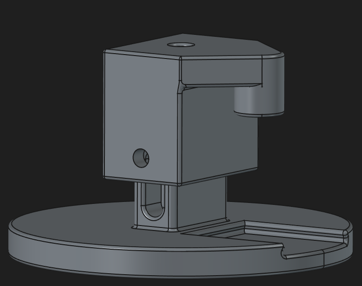
With this version, I’m going to see if gravity is enough to make the bottom part go back down. If not, I’ll try adding a pen spring around the endmill that attaches to the collet. With it meeting up with a rectangle, this will solve a problem with the original model where it wanted to spin a bit. The holes on the sides are for short M3 (or close-ish equivalent) screws to limit travel.
It’s binding a bit. I think once I extend the bottom piece a bit higher and reduce the gap between the sliding pieces, it will work. The pen spring definitely helps.
I have been able to lightly sand parts that slide into another and make them slide much smoother. I think it just smoothes the layer lines out and makes a noticeable difference.
The idea of mapping the spoilboard has been discussed a few times in the forum, and from what I recall, generally hasn’t been met with overwhelming enthusiasm. Personally I’m a bit agnostic on the idea, but I have a few questions and thoughts. These aren’t criticisms, more just curiosity about the pros and cons
Re: the concept of automatic bed levelling:
My experience with automatic bed levelling has been on 3D printers using Marlin UBL. Does FluidNC have a similar feature?
From what I recall about UBL, the maximum grid matrix is 15 x 15. Presumably you would want to keep the matrix spacing consistent between the X and Y axis, so let’s say 8 x 15. Spread over an 4’x8’ cutting surface, that is about every 6.5", with a total of 120 probe locations (which will take a fair bit of time and patience). Is a 6"+ spacing adequate to capture all of the variations in an unlevel surface?
On a 3D printer, once the bed is mapped, conditions won’t change much (glass or aluminum plate doesn’t warp much over time), but most LR tables are built of wood, which swells and warps as ambient temperature and humidity change, and as the wood seasons. I wonder how often will the bed mapping need to be performed?
Re: your tool:
It looks like you are using two 1/8" bits in your design. Presumably one would re-purpose some broken bits instead of needing to “waste” new bits.
The base seems unnecessarily wide (large diameter). Such a broad base might theoretically miss some low spots by having the outer edge contact the surface before the area under the probe does. Would a smaller diameter be better?
I’m interested to see how this project progresses. Best of luck!
I have no intentions of doing automatic bed leveling. FluidNC doesn’t support it and I’m not sure it would even be a good idea. My table sits on saw horses. So, I would potentially use this to shim it. I think once you get it as good as you can with shims, at that point, one could consider surfacing their spoilboard. This would let you know where the high spots are and how much you need to remove.
From here, I plan on making a FluidNC extension and/or a web page you can run off the internet connected via a Websocket. It would allow for defining grid size and provide a visualization of the bed. Perhaps it could even create the gcode for leveling the bed. Maybe you just want to remove the worst of the high spots without investing the time of surfacing the whole thing.
That is exactly the intent. Otherwise, you can buy a 1/8" rod and cut it which is $1.79 at my local hardware store.
This was done intentionally. The idea is that if you have a used spoilboard, using a small probe would be misleading as it might go in a cut groove or not. My goal is not to get some perfectly flat spoilboard. Good is good enough.
This is still an experiment. I don’t yet know if or how useful it will be. Unlike some other projects, I didn’t have to buy anything.
The parts list includes:
~ 20g of PLA
2 M3x6 screw
1 spring out of a pen
2 endmills (these happen to be new but I have some old ones I can use) or 1/8" rod
V1 tiny touch plate kit that I normally use for probing