New question that has appeared. Why are the firmware branches named either v1cnc or mpcnc? This got me confused and I somehow assumed that the mpcnc_ramps also was for the Rambo. So I spent a long evening troubleshooting the faulty firmware, even wrote a long post about it, before I saw another category in the drop-down list, namely v1cnc. I don’t want to complain, because I’m eternally grateful for this awesome project - I just want to share the word, in case others stumble on the same issue.
I think @jeffeb3, @jamiek (or was that someone else?), and others are helping @vicious1 get some sort of continuous integration going, and to help facilitate that, they set up the v1cnc branches for Jenkins to work on. If/when that comes to fruition, new updates will be automagically built for all configurations my the CI system, and Ryan only has to deal with keeping the configurations up to date, and merging the core Marlin codebase. Jenkins will compile and package all the various releases (RAMPS, Rambo, Archim, MPCNC, LR, Dual Endstops, etc., etc)
tl;dr - The v1cnc branches are likely the newest versions. At some point, it will make it easier to have multiple configurations automatically built when new versions of Marlin are released and merged.
1 Like
Sorry the new versions are V1***, there should be no overlap. V1CNC is for the LR and MPCNC, I only changed the name because so many emailed asking to send them the LR firmware not knowing they were exactly the same.
If I made a new version for something and it has been tested I remove the old version. Firmware takes way longer than it seems like it should. I think I am more than half way through the transition at this point.
1 Like
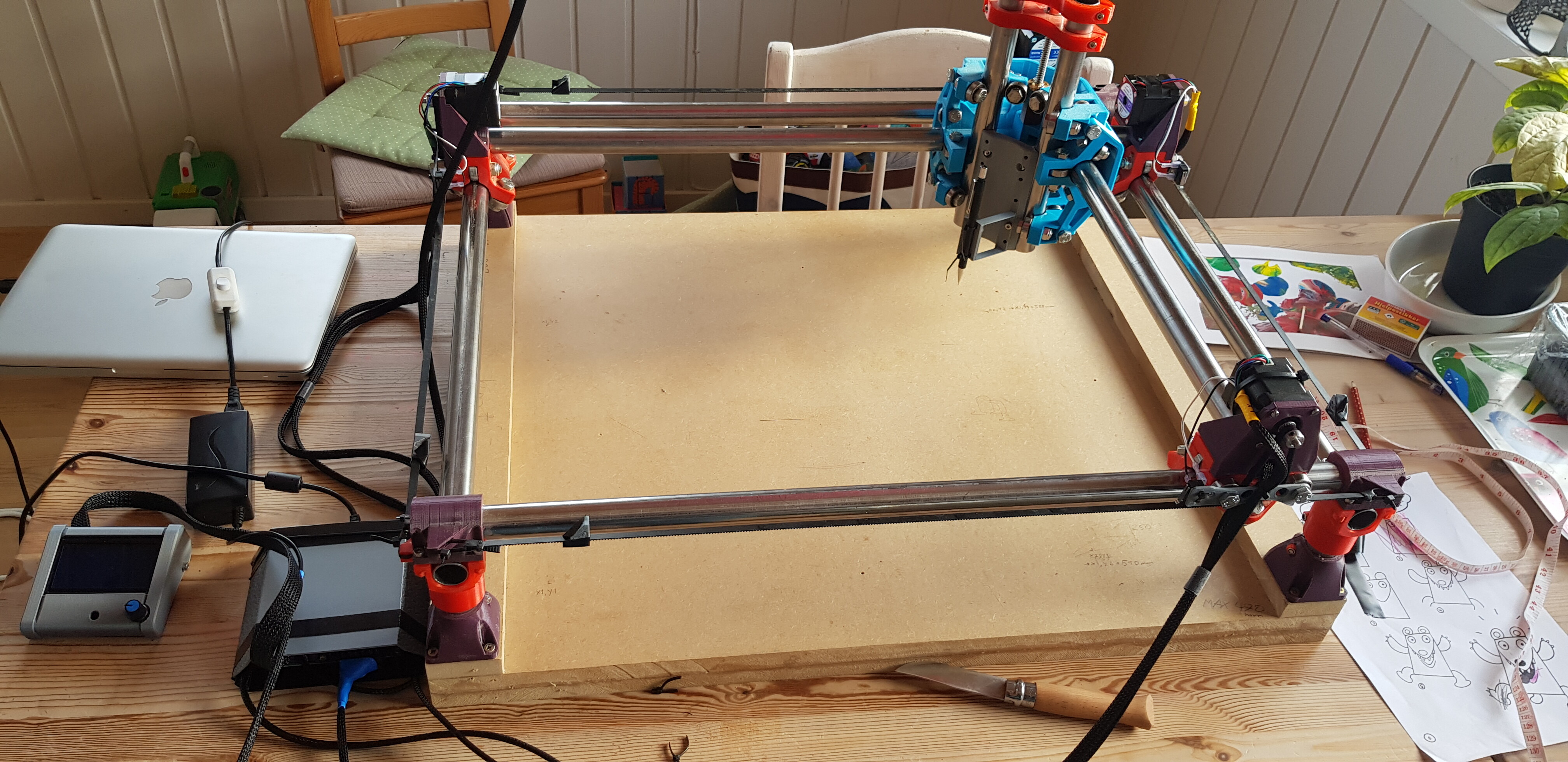
So - now the endstops are in place, wire harness is fixed, and everything figured out quite nicely! I’m super happy with the finish, even my wife is impressed. Now I’m going to offset the end stops to get it as precise as possible. I don’t fully understand the guide in the docs… please bear with me…
Here is the current build:
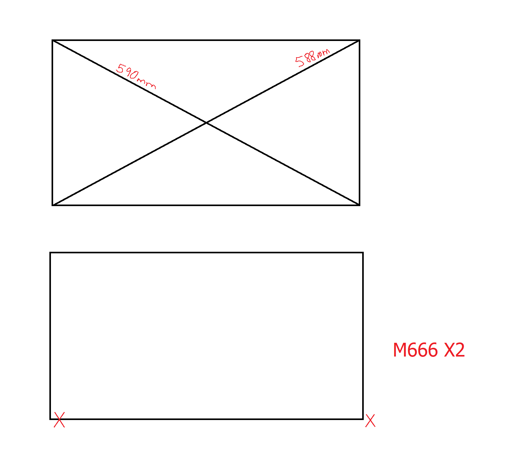
I’ve named the bottom left corner X1Y1, bottom right corner X2Y1, upper left X1Y2 and upper right X2Y2.
From X1Y1 to X2Y2 it is 588 mm
and
from X1Y2 to X2Y1 it is 590 mm.
Where to I add the offset? X or Y? My head is zizzling, trying to wrap my head around the geometry…
EDIT: Okay - things seem a little clearer now. I’ll try this one, after having put the kids to bed:
- Offset the endstop that has the short dimension by the amount it is short or just a hair over. So if the X1 diagonal was 1mm short you would offset X1 by 1mm. M666 X1. Tip – If it is more than 2mm off move the stop block, each belt tooth is 2mm.
Okay - I tried M666 X2, it seemed like the right thing to do. But it didn’t help, it just moved the two x’s towards right. The two top corners of the rectangle didn’t adjust. I don’t understand what I am doing…
Sounds like a Tuesday around here…
They used to say that we shouldn’t play with that number!!
That’s a different story altogether, I was just talking about the general concept of not knowing what the &$*@! I’m doing at any given moment…
I haven’t done them myself (still printing parts), but I would think you’d do the X axis pair separate from the Y axis pair. You’re trying to get both X endstops set so when they are triggered the X axis is perpendicular to Y, so you’re moving 1 X endstop to align with the other X endstop. Then repeat the process for the Y endstop pair.
When you’re all done you should end up with equal diagonals, but trying to work from diagonal measure to start with makes my brain hurt.
Like I said, I haven’t done my own yet so if I’m talking nonsense feel free to tell me so.
Aaah - my head is really popping like popcorn now. Nothing makes any sense, much like @kvcummins regular modus operandi… OOOkay - now I’m having a little brake through here!!
Bear with me:
The x1 endstop is with M666 X2 told to offset zero 2 mm towards right, on x1 motor side(bottom). Makes sense looking at the second picture.
I’m sorry for all my ramblings. Light is dawning upon my troubled mind. I think I’m figuring it out. I think I’m just confused by the tutorial in the docs: https://docs.v1engineering.com/electronics/dual-endstops/
The Y-axis is the perpetrator. I even moved a stopper a step, to see how that affects things. Thank you all for your consideration, I’ll be back when the dust settles…
The counter intuitive part is that just about anything you do will make it better or worse, and there is no real right answer. You are adjusting the angle between X and Y. If you move the X2 motor offset, it will adjust one axis. If you adjust the Y2 motor it will adjust the other axis. They both adjust the angle between X and Y. If you can’t visualize it, you just have to trust me.
So just adjust one, see which way it goes. If it gets worse, try doing it the other way.
M666 X1
Should make it move the X1 motor away from the endstop 1mm after homing.
M666 X2
Should make it move the X1 motor away from the endstop 2mm after homing.
I think you can do M666 X-1 and it will move the X2 motor away from the endstop 1mm, but I haven’t tested that.
3 Likes
You can use negative numbers on the M666 and it will move the other motor away from the endstop.
3 Likes
Dang…you really do learn something new everyday. That is awesome!
1 Like
Thank you guys for your patience… I actually ended up physically moving the stops and finding a better spot, using the hard stops. Now the diagonals differ about 0,5mm, and the angles seems quite square. So, for now I’ll keep it like this, and bring out the M666 when the day comes where I need even more precision. But it sure was worth it, it’s super simple to get the machine booted and squared now! I think that my head is a little clearer as well, about the whole geometrical concept. A good process, all in all. 
G28 for the win!
2 Likes

WHOA…
It was like 90 here.
I’m afraid that all the snow around the house won’t be gone until June…
Yea, we always had snow in the shady spots until April in AK.
Ah. But you get to see the Northern Lights.
We could see the northern lights in Arizona on year very beautiful