Finally I have some time to share with you the first steps of my Primo to LR4 conversion.
I built my Primo in 2020 and had a blast building and using it. The work area was around 30" x 21" (751 mm x 490 mm to be exact ![]() ), which was mostly ok, but depending on the material I had to deal with some chatter.
), which was mostly ok, but depending on the material I had to deal with some chatter.
Printed Parts
But when I saw the new LR4 design, I couldn’t resist from converting my Primo. So I ordered some spools of material and started printing the parts. And thanks to my quite new Bambu P1S (which I totally love by the way…) it took only a few days until I could marvel at these glorious parts.
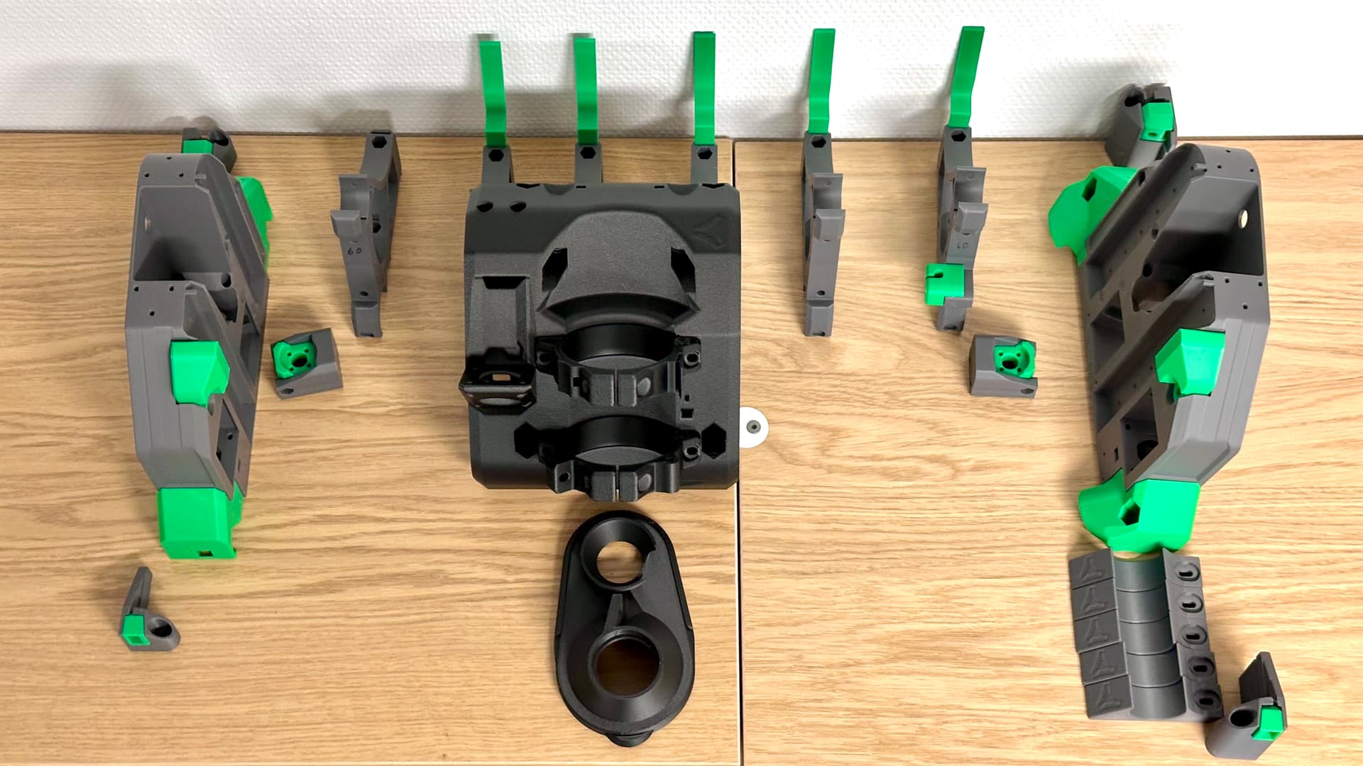
To @vicious1 and all beta users: what a nice thoughtful design. Those parts feel so massive and sturdy. Wow…
I know that it’s not needed, but I printed the core and everything that is attached to it with PET-CF. Purely because I wanted to know how well it prints on my bambu. And boy do they look nice. They came out flawless. Again, great design.

So now with all the printed parts ready, I started thinking about all the rest on the shopping list.
Build size
I going to reuse the table I built for the Primo which, according to the calculator, gives me a max work area of 800 mm x 600 mm. And yes, I am going to build it with X larger than Y. It just fits better in the workshop.
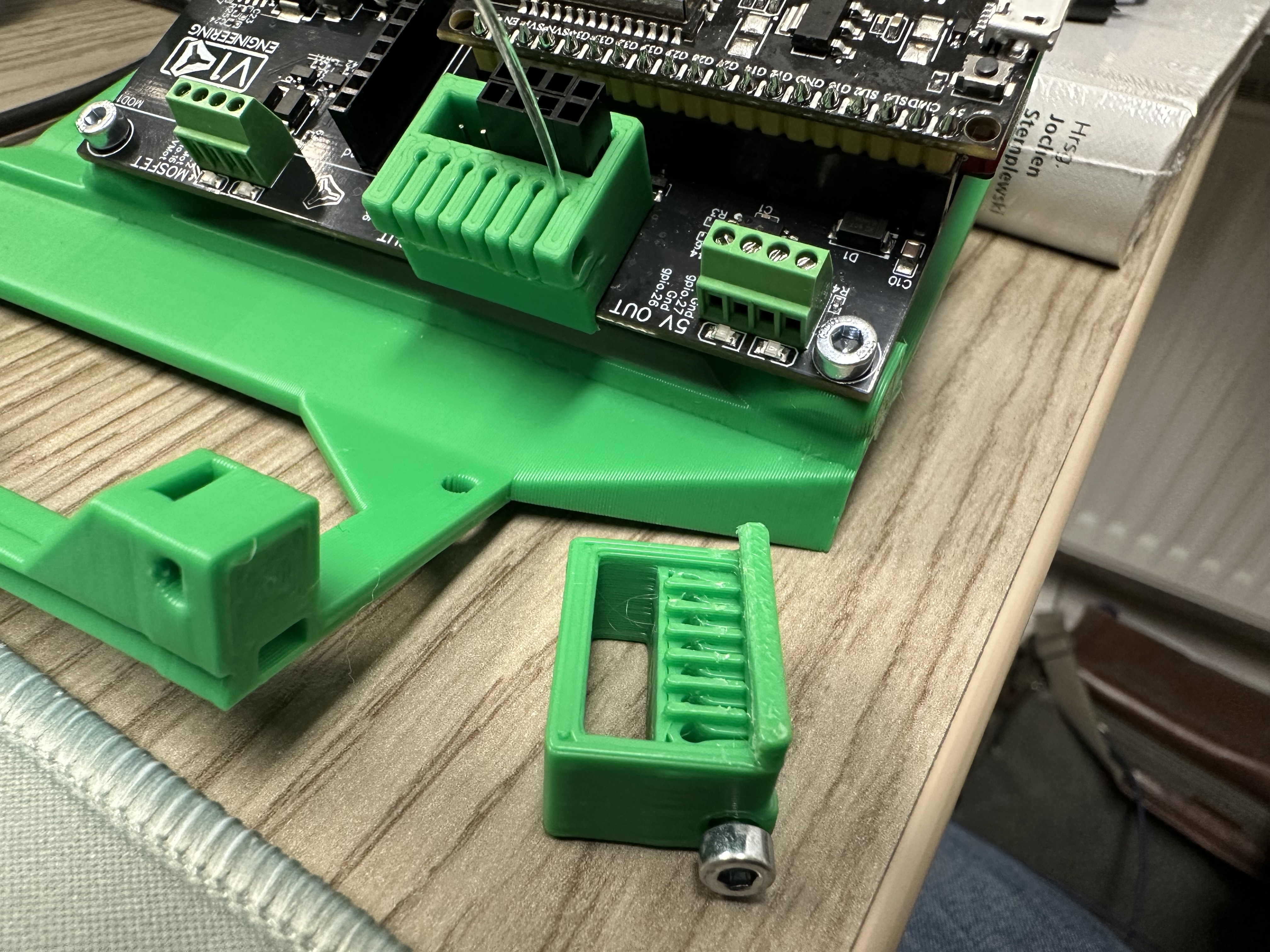
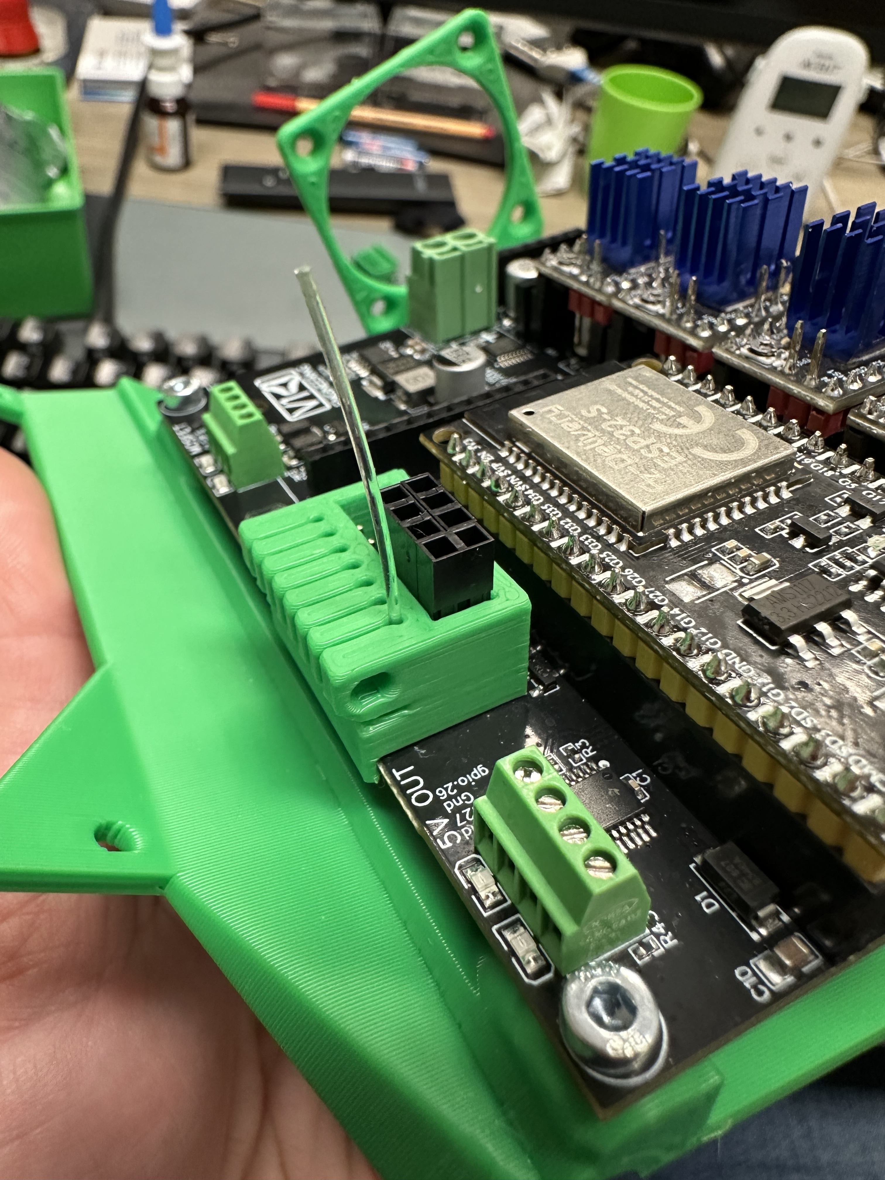
Controller
On my Primo I used a Arduino Nano Estlcam shield, so I could use the controller part of Estlcam which I really like. The problem is, that estlcam shields only have 3 independent axes (XYZ). For the Primo I ran two stepper motors on one driver for X and Y which worked nice. But you do not have auto-squaring, which is not needed for the Primo.
Now for the LR4 I orderd the Jackboard from Elecrow, so no more Estlcam controller. I am exited to see if I like the workflow with FluidNC.
But I couldn’t stop here. I already ordered a CYD and a CNC Handwheel to build @Fab_ster version of the pendant.
Pipes
The bigger the better, so I settled on 32 mm non-stainless pipes with 2 mm wall thickness.
XZ-Plates
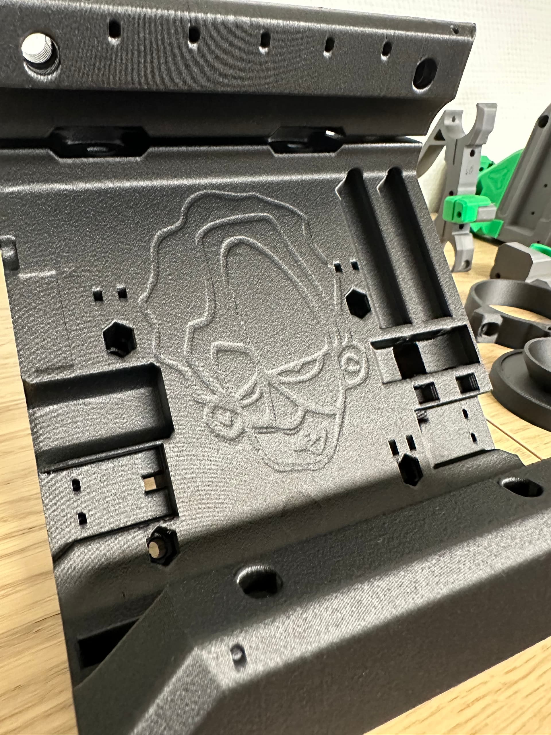
While I was waiting on the electronics and other hardware to arrive I went to the next challenge. maschining the aluminium plates. So I ordered some 6 mm AlMg3 (EN AW-5754) and gave it a shot. And hey, I only broke 4 bits during that job, but I finished with two correct sized YZ-plates.
- 3 mm 2-flute alu bit: broke right away on the test cut, because the z feed rate was to high.
- 3 mm 2-flute universal: broke on the finishing pass of the outline right in the edge of this little end stop finger. It is the only 90 degree inner corner on the piece and the sudden load change was to much on my primo. On the roughing pass I used trochoidal milling, so it was not an issue there.
- 3 mm single flute: broke on the finishing pass on the second plate in the same spot
- 1.5mm single flute: broke on the finishing pass on the min-plate on the inner edge of the pocket for the x-belt.
After that I did not have any bits left that could cut aluminium, so I had to skip the V1 logo pockets. Sorry Ryan, but I think I will order some stickers and put some of them there instead
Strut plates
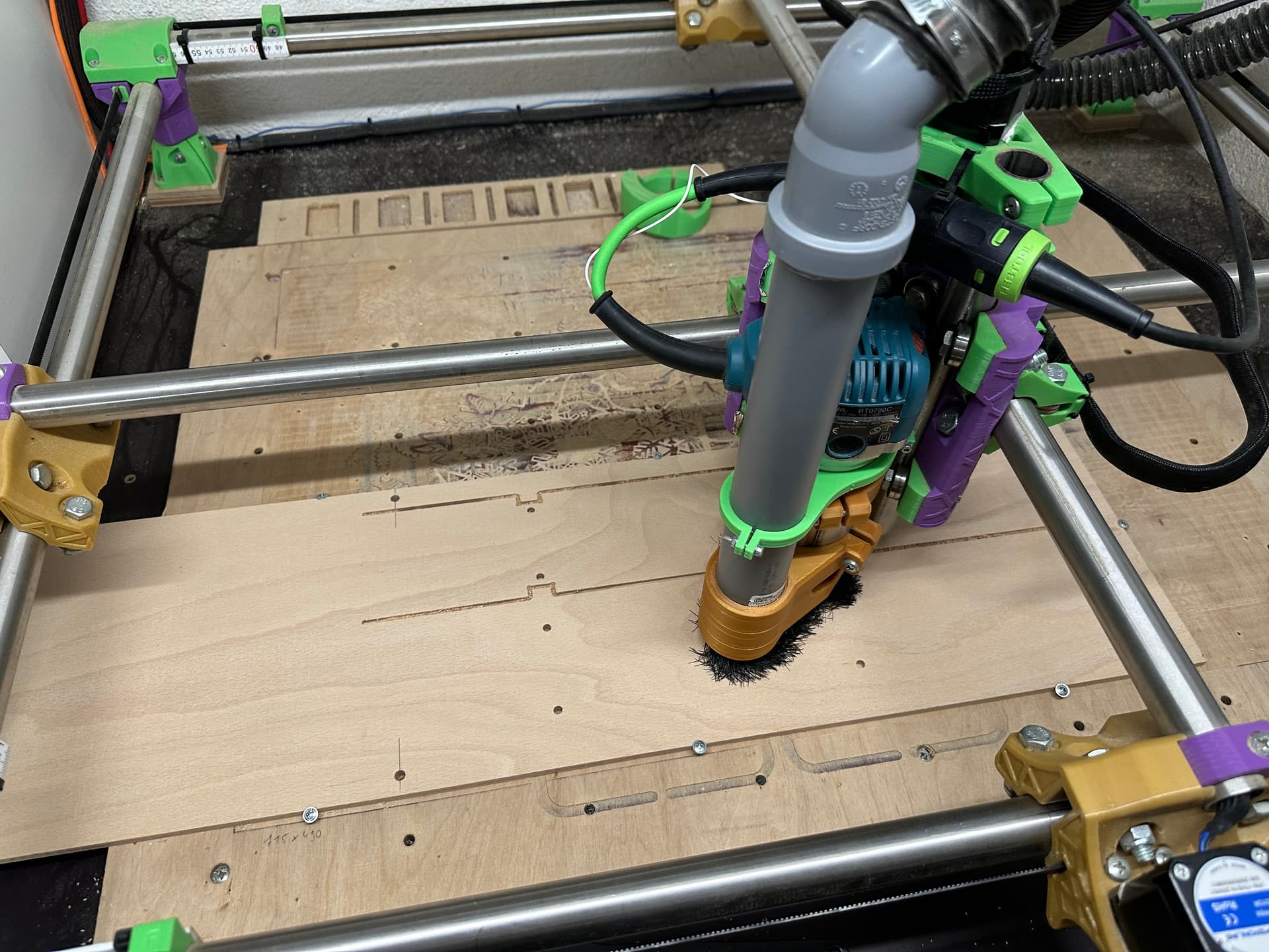
With my Primo still in working condition I started cutting the strut plates from 6 mm birch plywood. Because I only had 751 mm max working length and the strut plates need to be more or less precisely 969 mm, I had to do the cut-flip-cut with dowels trick. Thanks @Tokoloshe for the tutorial on that. Worked without issues (no broken bits this time ![]() ). Because my workshop has quite a high humidity, I coated the strut plates with some white paint I had still at home.
). Because my workshop has quite a high humidity, I coated the strut plates with some white paint I had still at home.
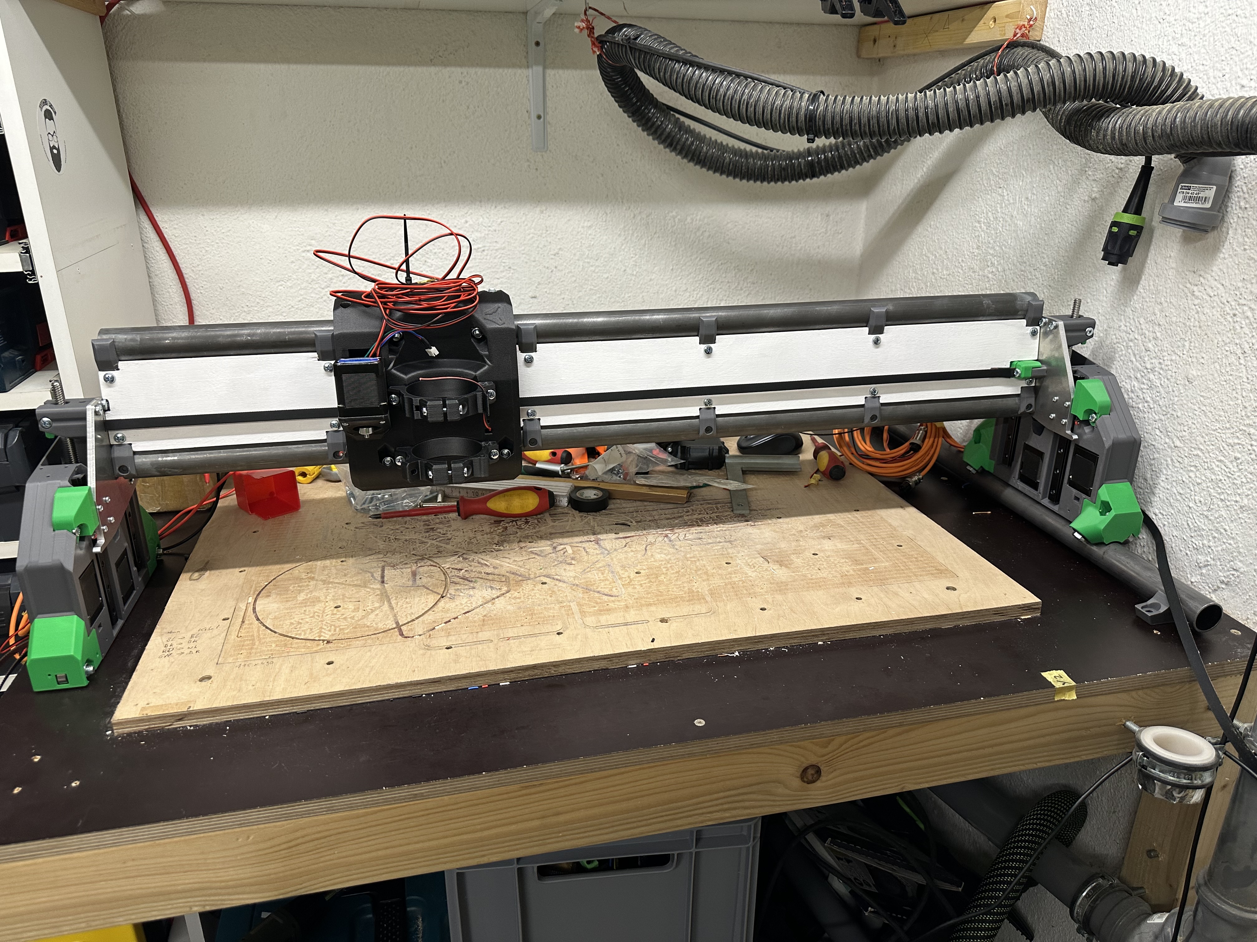
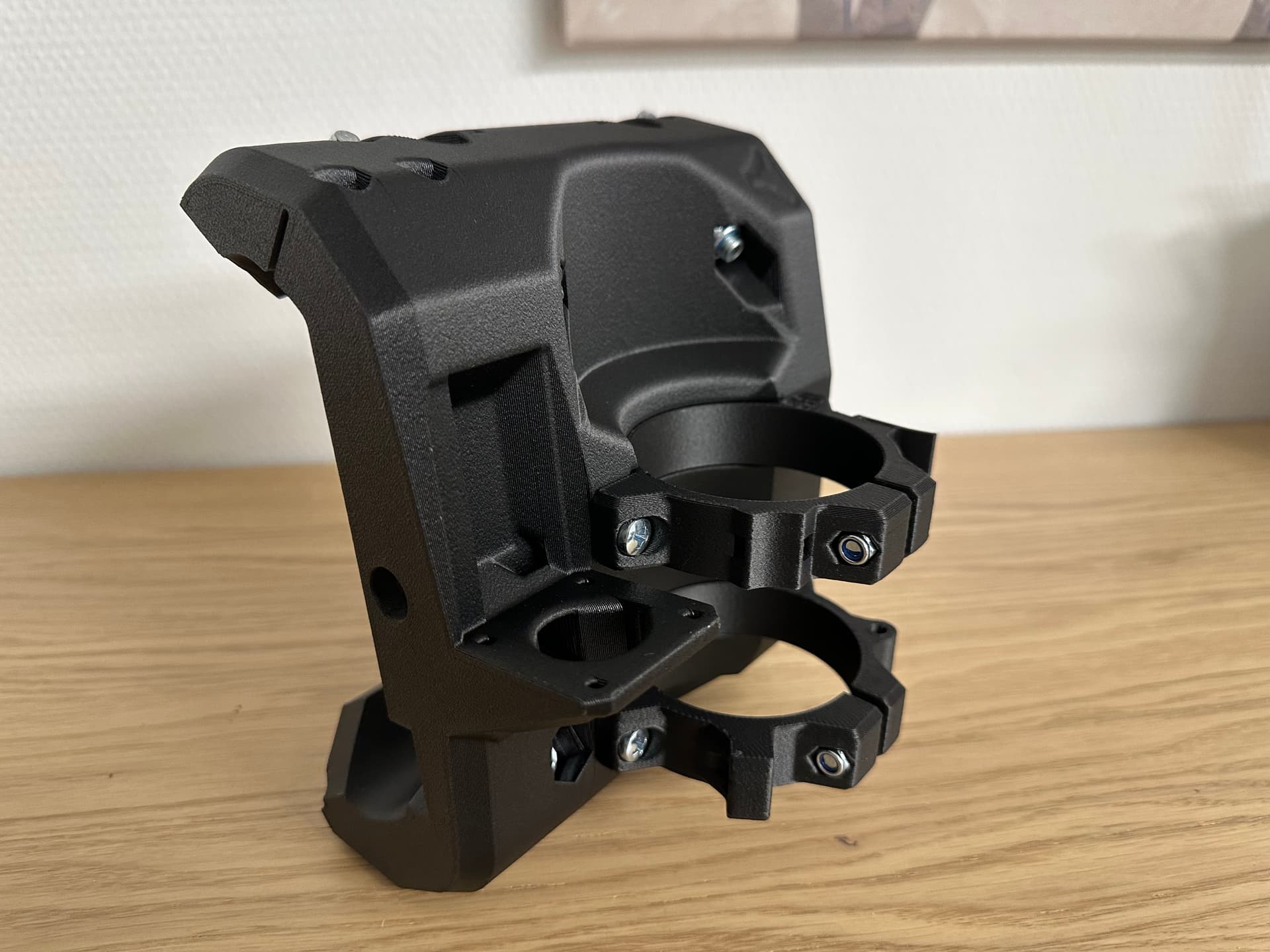
Mechanical assembly
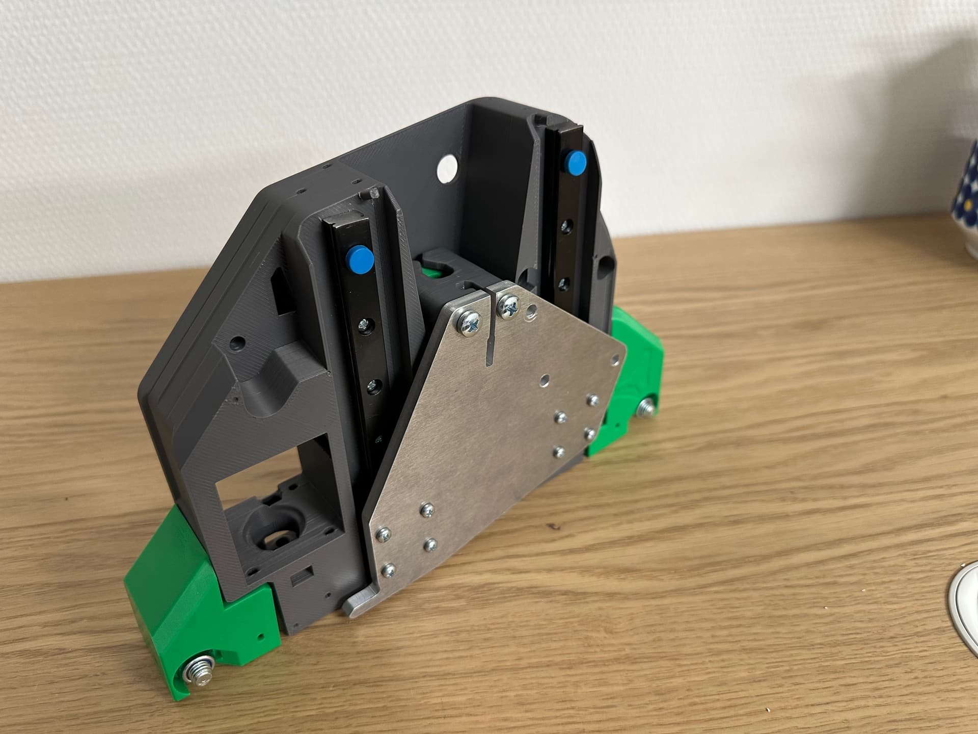
I didn’t break down my Primo yet, but was curious if the parts will fit together, so I started assembling everything mechanically. Ryan your design makes me speechless. The tolerances are so good, everything just slides together. ![]()
The moment I put the core onto the beam for the first time was unbelievable. The core rolled without any play on the beam. I couldn’t stop moving it by hand. That felt so nice and much much stiffer than my Primo.
So here are a few more pics of the current situation:
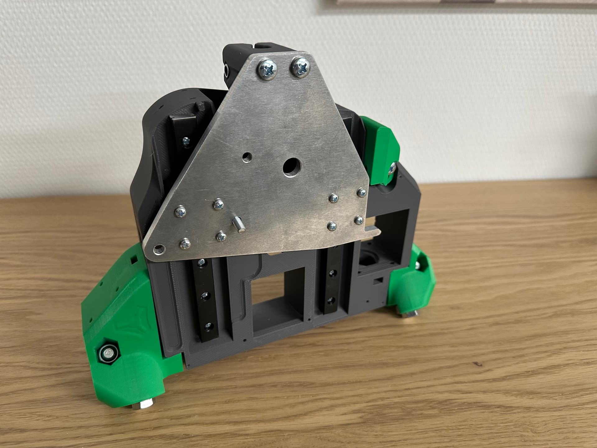
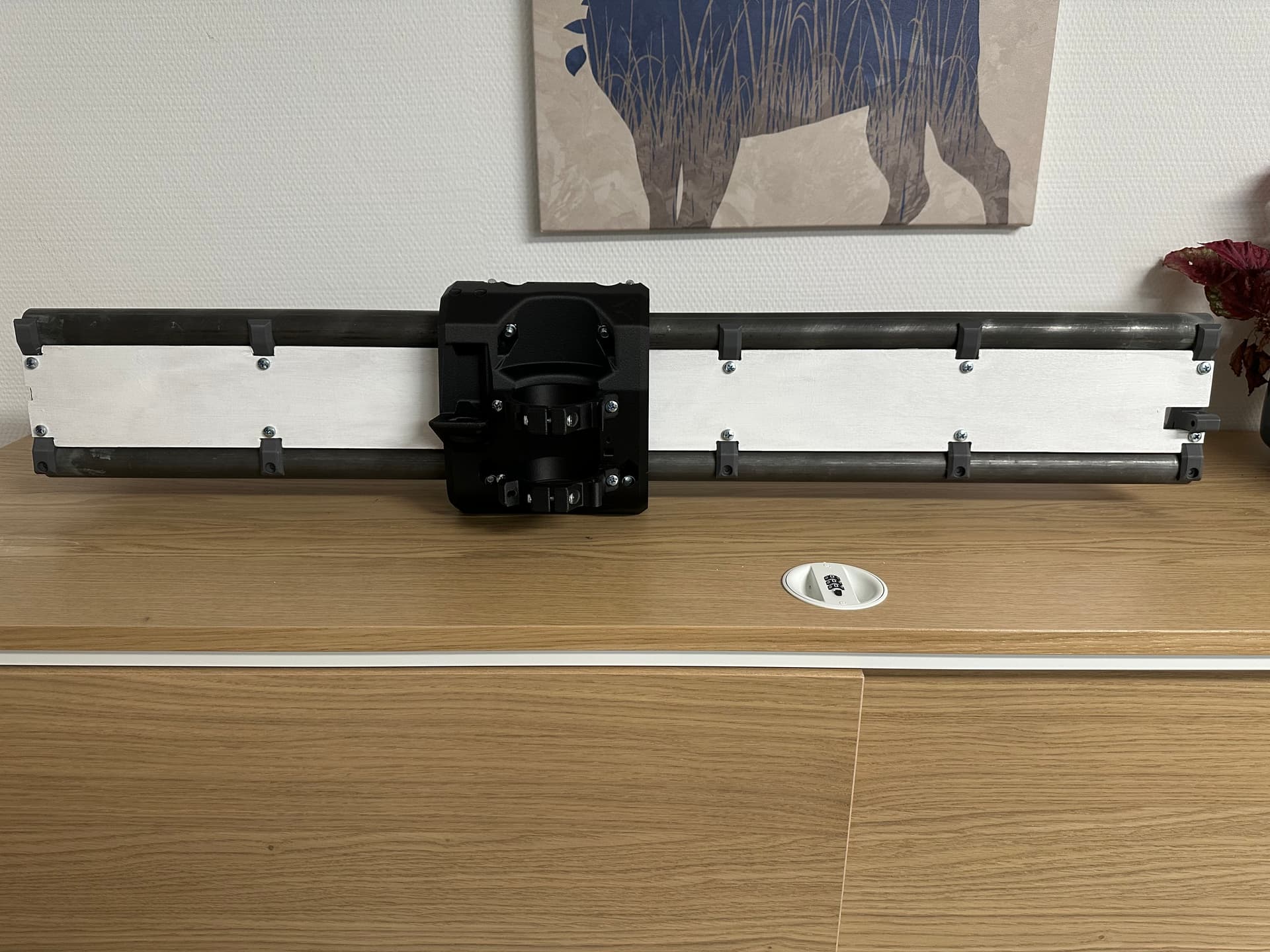
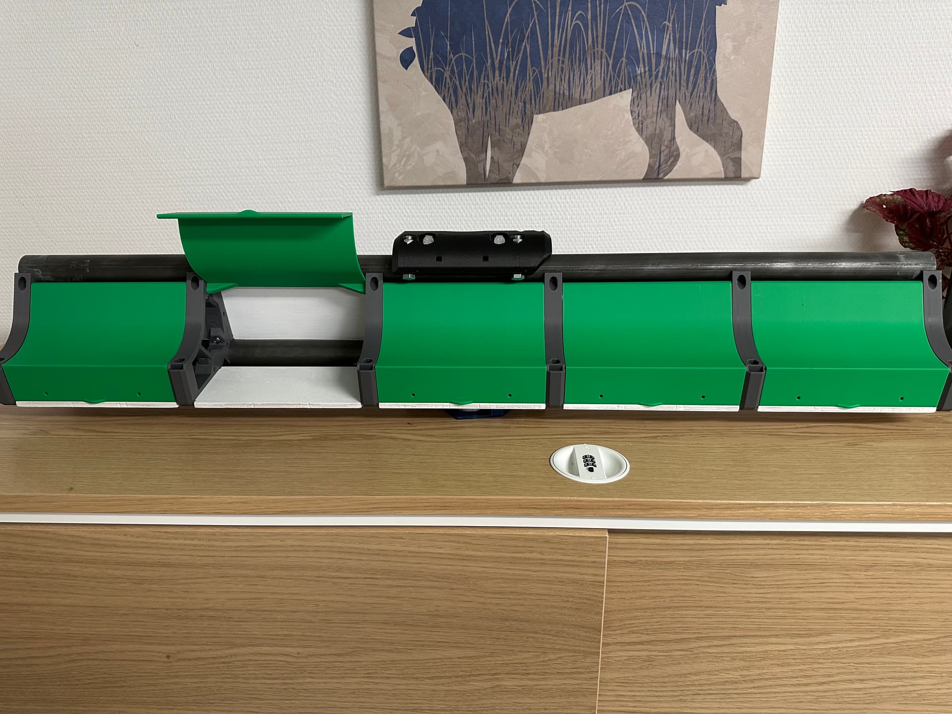
On the back of the beam, I will use the back plates by DougJoseph. Quite nice design, but they do not open that good with the 32 mm pipe. Maybe I need to trim down the top a bit.
Enough for now. Next part is to break down my Primo. That makes me happy and sad at the same time…