Primo MPCNC Build-Alabama 2023

Hey everyone,

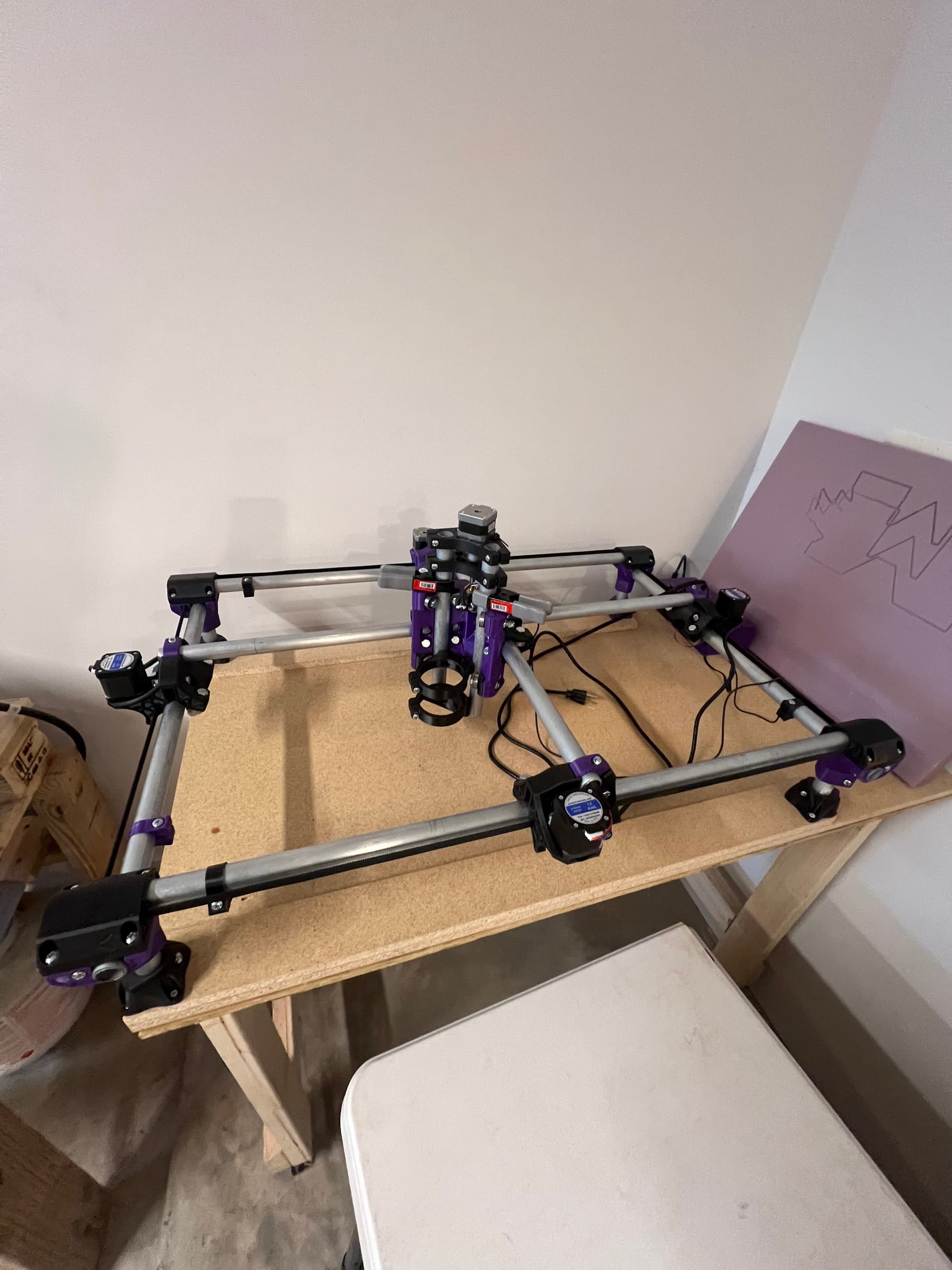
This build log may be different from most, as I have already built “most” of my MPCNC, however I plan on doing things a little bit different than most and wanted to share my experience for other to follow along.
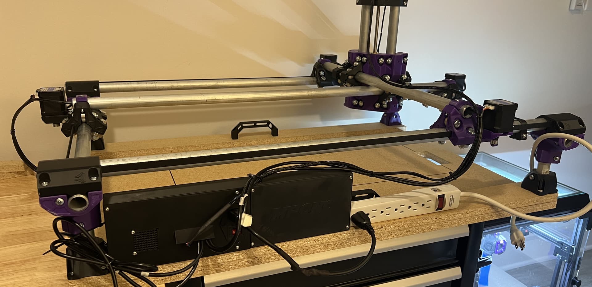
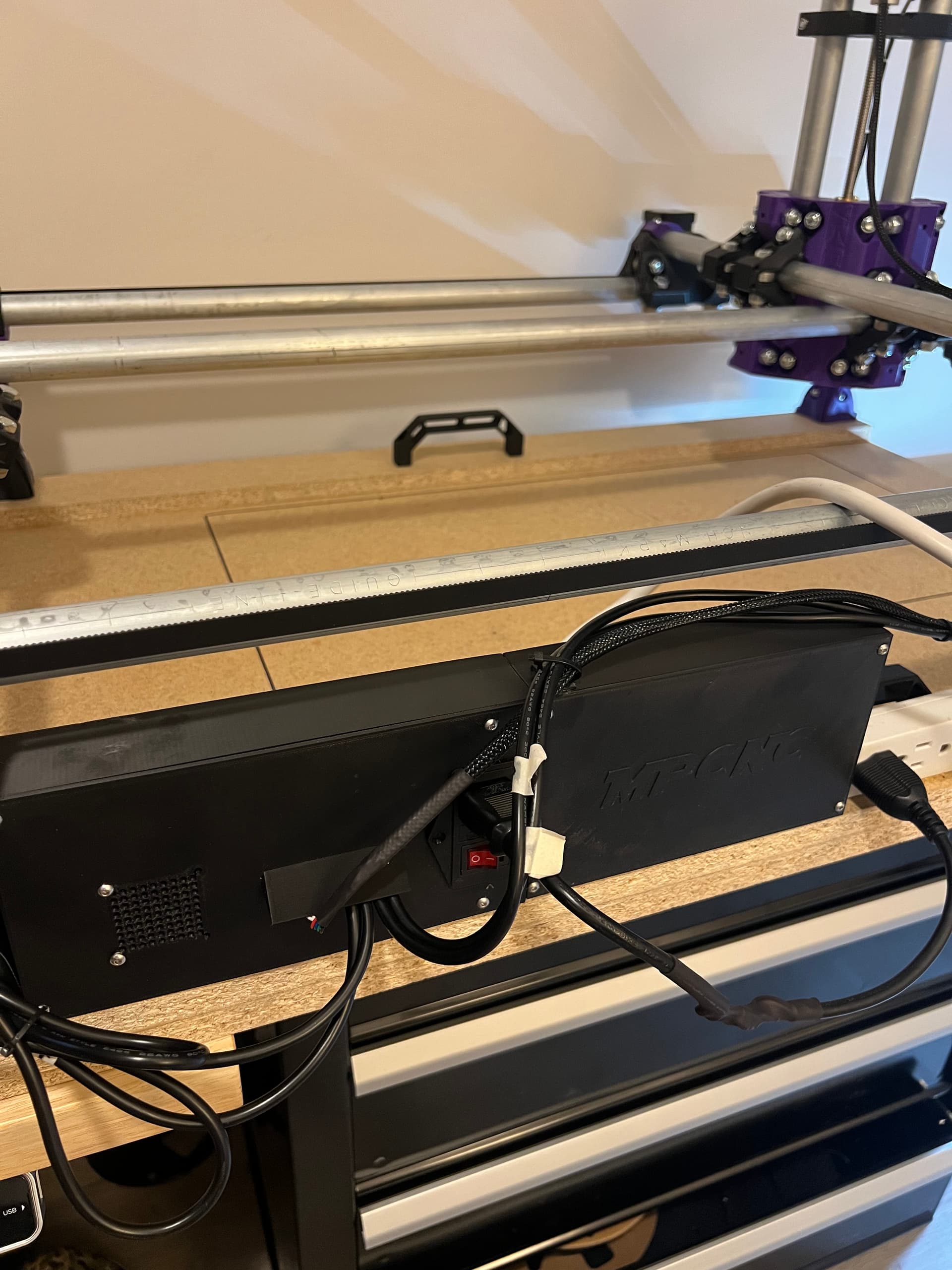
My main goal of this build was to keep cost as low as reasonable, and use as many parts I already had leftover from 3D printer builds/general maker items. This included the control board which is an SKR Mini E3 V2.0. I am running Klipper as the firmware, as I have quite a bit of experience with it, and really love how easy it is to configure/change.

I chose approx. 25in x 13in for the work area because that makes the build table a perfect 36in x 24in. I used a 2x4ft sheet of particle board as the base, which leaves 1ft left for control board/power supply storage/tools.

For printed parts, I chose to use ABS rather than PLA, which I know may be against the standard practice from what I have seen. Given that I am in the Southern US, and this MPCNC will live in my garage, I didnt want to get any warping or melting in the hot summer. I printed everything on my custom Voron Trident, which prints ABS exceptionally well.

I have slowly been learning how to use Estlcam and I understand the basics thus far. I was able to successfully drawn “the crown” test (sorry didnt take a picture).

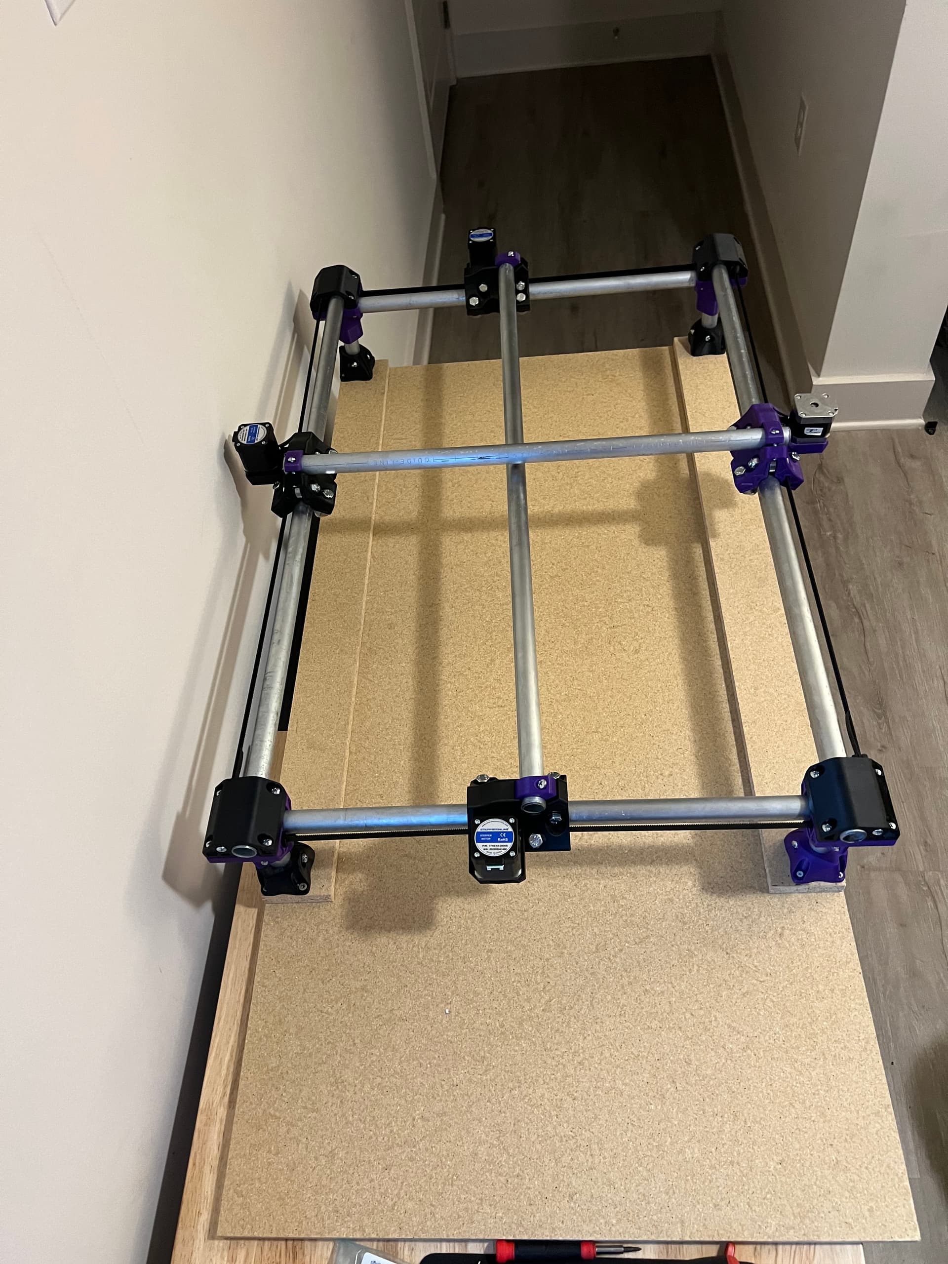
However, after that job I ran into an issue with the y axis. It starts to “bind up?” and only one side of it will move like 3mm and then get stuck, as the conduit is at a slight diagonal. I have tried adjusting all of
the bearings/nuts on each of those trucks, but the issue persists. I was wondering if anybody else had a similar issue. My only other guess is that it is related to the belt tension not being perfectly even
on both sides, not sure how vital/exact that needs to be. I am afraid I might have to take everything apart and rebuild, but very carefully go through and adjust each of the bearings to be perfect.

Anyways, I have a bunch of plans for upgrades, and will continue to post as they come along! I want to thank everyone here on the forum for being so nice and extremely helpful. If you have any tips, suggestions, or questions please feel free to ask away!

2 Likes

Check the grub screws of the pulleys. If they are not tight on the shaft the other motor drags the one with the faulty screw behind.

Very nice build. I would run it a bit, trying to learn and shake out any small issues. I agree with Philipp about the grub screws being an issue. Check all bearings contact the tubes, but not too tight. Get in the habit of doing a preflight check before each job, as nylock nuts, contrary to popular belief, loosen up from time to time.

Congratulations on the build and we look forward to seeing what you make!

Thanks for the advice! I will try all of that once I get some time after the holidays.

Another question/note:
Like I said in my original post, using the V1E calculator, I made the workspace a size such that the “Table Size” works out to 36x24in. The workspace size says 25.25x13in, however I have noticed that I actually have around 32x16in of travel from the core (workspace size?). I’d imagine that the calculator measures from the center of the tool holder aka where the router bit would be, but I still think I’m getting a larger size than anticipated. Not necessarily a complaint, just curious if I have built something incorrectly, or that is just the way it is.

That is weird. I built mine to have a 24x36" work area. I’ll double check my dimensions tomorrow. There is some extra travel beyond the working area, but not much. It could be my memory though, so I’ll check when i run it tomorrow.

I built mine to be 25" X and 37" Y work area.

And that is what I get for movement, minus the teeny bit that leaves between the end of possible movement and where I have the endstops.

My actual table is 42" by 49" with some extra outside the feet (mostly in X)

I do plan to rebuild the Primo for a smaller (and more rigid!) work area, still haven’t done it…

Oh yeah, I agree 100%. Sadly, I really only ever use 1/4 of the work area on a regular basis.

I just got my two 850mm 9mm MDF plates from the local hardware store for a mini torsion box I can carry into school. :smiley: Workspace will be 450x450mm (so it can later theoretically fit an IKEA Mala roll for a 30m drawing). :smiley:

Well, quick update on my current progress. Got busy and haven’t been able to work on it, but finally got some time to iron things out before making some chips.

One of my main goals with building this machine was to make it as easy to setup and use, and as easy to move around/transport as possible, as I do not have much space to store it. Basically I want to make it as simple as possible to go from being in storage to being in use.

First, I originally used a 2x4ft sheet of particle board for the base, with the MPCNC being built on a 2x3ft frame, and the extra ft being used to house electronics/controllers. However, I cut off the last ft of board as it was a bit unwieldly to carry around, and it made the whole thing a bit akward. Instead, I designed and printed an enclosure to house all the electronics under the back gantry rail. It holds the 150W MeanWell PSU, an SKR Mini E3 V2, and a Raspberry Pi Zero 2 W, which is all of the electronics for the MPCNC.
I really like how it turned out, as everything is sealed well and not going to move around. I also added a power strip directly next to it, so that I can plug in the electronics, router, and vacuum and only have to plug in the single power strip cord to run the entire machine. I only have to flip on the power strip and I can be up and running.

I made a whole new wire set for the steppers with some 4 conductor 22awg wire. This gives a really clean look, and I personally have never been a fan of cable chains, so I opted to zip tie them to the base to allow full travel while not getting in the way. The y axis cables are a bit long, and I may shorten them to proper length in the future, but for now I just looped them around and zip tied them to the foot.

I did a quick test run with a sharpie, and drew out the maximum build area on the base, so that I can quickly put a workpiece down and see if it fits within the bounds of the MPCNC.

As I said in my first post, I am running this using Klipper Firmware, as I have a deep background with it from 3D printing, and I really enjoy using it. It is super easy to set up, and I think the best feature is being able to control my entire MPCNC from just a web browser on my phone, iPad, computer, or whatever. At some point, I plan on maybe getting a touchscreen display to be able to directly control from the machine, but pulling out my phone is just about as easy.

Once again, feel free to ask any questions or provide some insight!

1 Like

Do you still see that 32x16 travel with the router and end stops installed? I guess if that’s what happens on mine. I can shrink it and make it more rigid!

No, given how well everything else is designed, I should have assumed the calculator was correct. My workspace is about 25x12.5in. Just a rough guess. I think when I originally said I was getting a bigger workspace, I wasn’t measuring from the actual center of where the router bit/pen/tool would be, but rather the travel of the core itself. I got that measurement from looking at the X and Y coordinates on the firmware, with X being max of 800mm and Y being max of 400mm, which roughly works out to 32x16in.

Measuring the size of the sharpie box I drew going to the max position, which is where the router bit would be able to cut, is around 25x12.5.