So up to now, if I positioned my zero point"close" to the front left corner, I had plenty of wiggle room to make all my cuts… Now I’m cutting 2 new full sheet torsion box frames for 2 local high schools. The struts run the full 96" so it’s super critical that I have that home corner spot on.
Can anyone share their zeroing process with me?
Thanks!
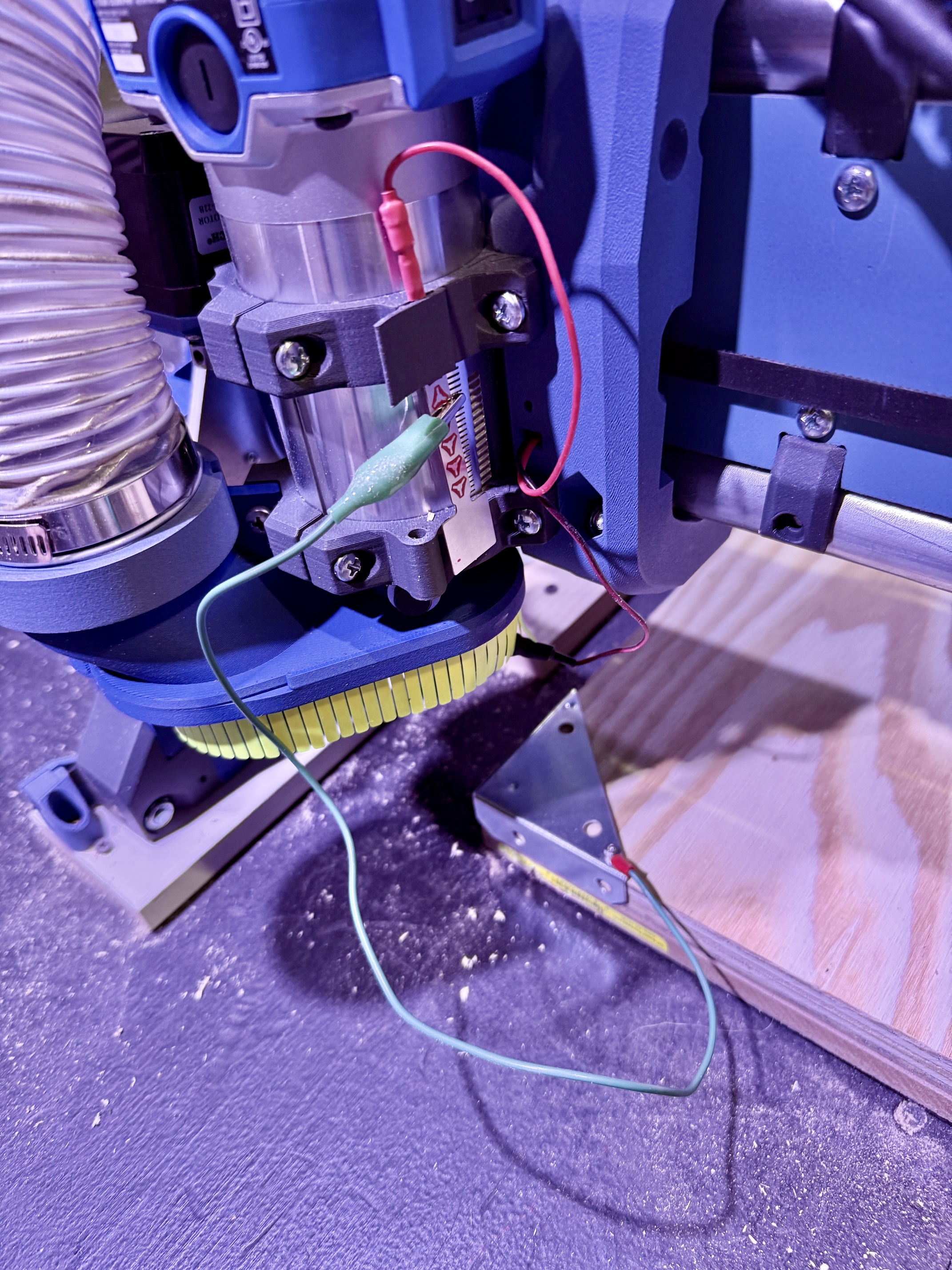
Follow up, Dec 20th, so I tested my “cheap- no milling required” 3-axis probing block and gcode last night. Albeit this was on bootstrapped rails screwed to the stage floor so that we could cut the torsion box frame. The probing plate and g code worked perfectly after minor tweaks.
Here’s a pic of the setup… Simple and easy to use when necessary.
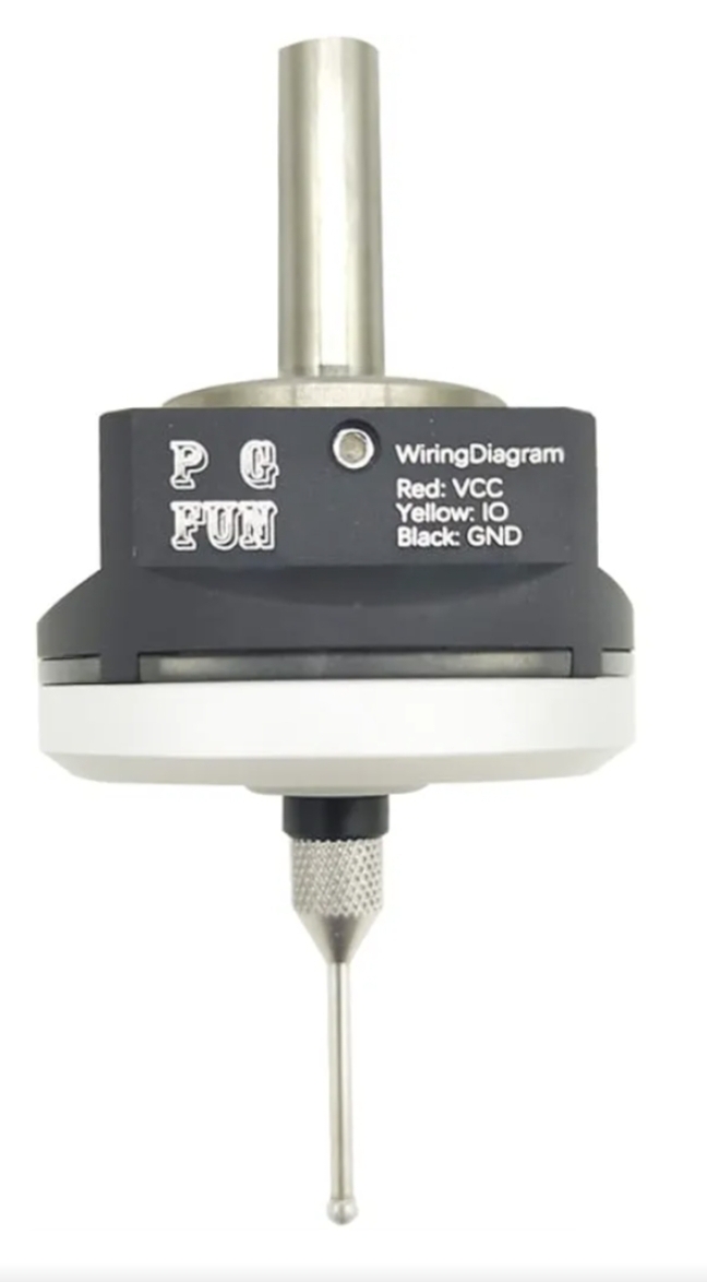
You can actually probe X and Y like you probe Z. I think this means you need to offset for the bit width. I wrote some gcode to do this once, but I never fully tested it. They make fancy probes for this, but I just did it with the tiny touchplate.
Since no one jumped in I’ll tell you what I do. Listen to whatever someone who’s actually doing this tells you… but here’s my thoughts:
My LR4 has a cutting area that’s just about 24.75" x 61". I sized it slightly oversize for working with 2 foot wide materials.
I don’t usually have to be super precise or repeatable for my hobby projects. That said, I planned for this possibility by making a little spacer that I could line up along the Y axis riser on my build. That would let me position the work piece so that the router bit can go fully outside of the work piece in both +X and -X.
I haven’t used it yet, but I also made a stop block that I’d place on the spoil board so that between the spacer and the stop bock the work peice would be entirely within the cutting area.
(0,0 would be at least one router bit below and to the left of the 0,0 on the work piece.)
I’m not sure this is actually helpful to you as I’ve yet to use this in practice.
Yes, the jackpot and fluid NC. Do you still have the gcode for probing the 3 axis? I’d love to have that available to zero easily… Actually I guess it would be better to know how you set up that gcode since the thickness of of whatever I mill up as a corner touchplate will need to be figured into the code…
I found it, but I wouldn’t use it. I see I last modified this in January, 2 months after I built my Lowrider (my first foray into CNC). I was just trying to learn gcode. I didn’t actually even run the gcode as a file. I was running it manually line by line. It doesn’t handle offsets correctly. I think you want more of the approach of MakerJim or Philipp. I like the aluminum tape idea too.
To be clear, don’t use this. Here is what I have, it has a bunch of comments. Maybe this will be conceptually helpful. I don’t think it does the offsets right and absolutely needs changes. It requires 10mm or 20mm extra space in X and Y which I don’t think works for your use case.
Gcode (Concept Only)
(Manually move over front left corner)
G21 (Use millimeters for length and speed values - G20 for inches)
G90 (Absolute distance mode)
G94 (Feedrate in millimeters [due to G21] per minute)
G92 X0 Y0 (Set current X and Y position as 0)
M0 (MSG Attach probe)
G38.2 Z-80 F200 P0.5 (probe down set thickness)
G1 Z10 F200 (Move Z up 10mm to get out of the way - position should be 0,0,10)
G1 X-20 F200 (Move X left 20mm to get to the left of the workpiece - should be inline with workpiece)
G1 Z-10 F200 (Move Z down 20mm to get below top of workpiece)
M0 (MSG Probe X left side)
G38.2 X30 F200 P0.5 (probe right set thickness)
G1 X-10 F200 (Move left)
G1 Z10 F200 (Move above workpiece)
G1 X10 F200 (Move over workpiece)
G1 Y-20 F200 (Move in front of workpiece)
G1 Z-10 F200 (Move in front below workpiece)
M0 (MSG Probe Y front side)
G38.2 Y30 F200 P0.5 (Probe forward set thickness)
M0 (MSG Remove probe)
If you care about getting a precise corner, you will almost always also care about having the stock square to the machine. Even if you use one of the methods outlined above to find the corner, if the stock is not square, the rest of the work won’t be accurate.
You can get stock square by constructing fences for X and Y. Personally, I just had my machine drill holes for pegs. I install my pegs, mount the stock against the pegs, and, optionally remove the pegs after the stock is clamped or otherwise fixed to the spoil board. I’ve seen others use rules for X and Y. The rules are mounted by pegs, and the faces of the rules are dressed by milling them with the machine. This assure the faces of the rules are square to the machine.
Now the “magic.” Whether you use pegs or rules, if you construct them using a known offset from a homed machine (i.e. no G92), then you will have the information to calculate the offset for the corner of your stock. There is a bit of calculation needed dependending on the method of squaring and the diameter of the bit, but you only have to do this work once (per bit diameter). After that, you can just mount your stock, then move to your calculated position.
Another less percise way to do rules is to have a v-bit cut a small grooves for the X and Y edges, then use the grooves to align the stock when mounting.
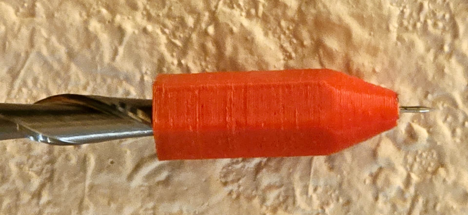
Another low-tech method I’ve used to find positions with 1/4 bits is a 3D printed endmill cap with t-pin inserted on the end. This is not as accurate some of the methods above, but it works for arbitrary positions, not just the corner of the stock. I’ve used this method to find the center of fixtures. I also use the cap to mark the home position on my spoil board so that if a stop block breaks or slips, I can find the current home again.
The pegs work great for squaring 1/4 inch or 6mm and fasten project down with blue tape and hot glue on edge. Full sheet projects i mark and screw the board down
Thank you, all , for your answers. The process makes perfect sense to me. Using tape or even milling a corner cap to zero to is simple enough. And if I was using Estlcam to drive my Lr4 the process would be cake. (maybe it is, and i’m overthinking) My hurdle now is how do I create gcode for this 3-axis zeroing (homing) that I can use with the jackpot board running Fluid NC. (It’s exactly what Jason was looking into and mentioned in the 1st reply to my question.) the only way I’ve created gcode is within Estlcam and that’s an automated function) Any additional tips are greatly appreciated.
Writing code is totally foreign to me. My biggest issue is lack of time. I’m literally writing in the forum between a F-ton of edits that i need to get out before I get tied up in the set build Tuesday through the rest of the week. I need to cut the table frames tuesday night… not a lot of time to learn and test code
any good “quick-start” resources on gcode that you could point me towards would save me a ton of time that i currently don’t have…
Thank you for help. Its appreciated more than you know.
I think to make it a bit easier on yourself and given the time crunch, don’t bother trying to write one gcode file that does it all. I would just use G38.2 to probe each direction. Then manually jog to where you can probe the next axis. It seems like you probably don’t need to probe X, assuming you have some wiggle room there.
Honestly, you can probably get close enough doing this without probing. Just jog (using small increments) and use G92 to zero that specific axis.
You’ll also have to be careful with your starting gcode so it doesn’t end up reprobing Z while you are positioned just off the workpiece.
This will definitely require testing with some scrap material.
The more I think about the things you have to get exactly right, the more I think you should just make the struts 95 inches long instead of 96. Or use MDF sheets which are typically 97 inches long.