Thought I would start a separate thread for this rather than cluttering up @dkj4linux thread. I started reworking @dkj4linuxManual Z-mechanism to use on the $79 laser engraver. After Amazon messed up my order, I decided to play with this design further to see if it would work better than my current solution of using a short V-Slot 2020 for the Z-axis adjustment on my other projects.
I really like the threading on this as I can use tolerances within Fusion 360 whereas using tolerances with normal threading has been a bit of pain for me. I tend to use openscad for any projects that need threading as thread tolerances are very easy with that. As many folks that use Fusion 360 for plastic 3d printed parts, I still haven’t understood where Autodesk does not have an option for this.
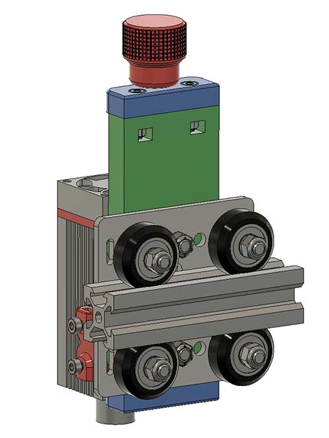
I think there was a previous iteration of this design using a nema17 for a real Z-axis. That might be where I want to go with this design but will probably need to beef it up a little & add some smooth rods. I am mounting it to this V-Slot Gantry Plate - 20mm - OpenBuilds Part Store
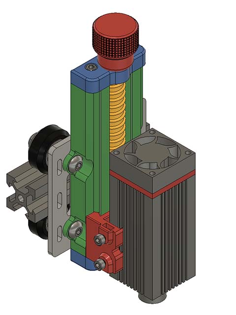
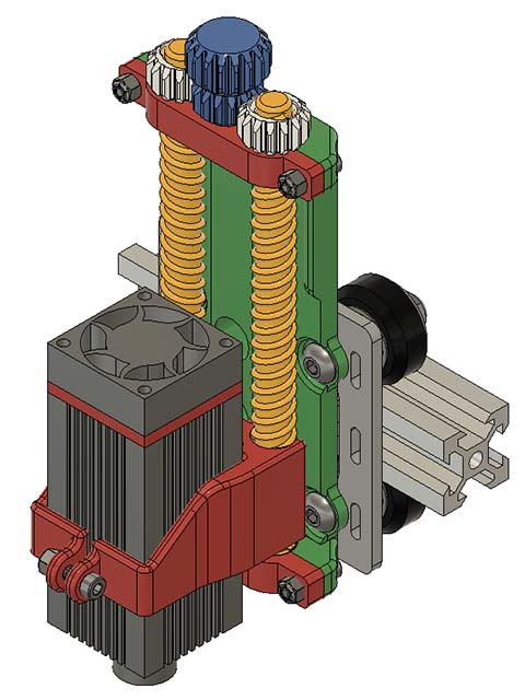
Here is what the design looks like so far. I had to move the laser mount out a couple mms or so for the wire connection. I added nut traps for M3 nuts on the side M3 screws to clamp against the laser. I am not sure I like that method as it seems like it might scar the finish of the laser, but not sure I can mount it from the back as I did before. I will try it like this to start with. I want to take a little more off the bottom of the green part as I loose 8mm Z clearance with that bottom plate. Looks like I have room to move it up some.
You may be talking of this one. I did a series of Z-axis mechanisms that started with a motorized version and then “morphed” into the version you’ve been playing with here. It went “manual” when I simply replaced the motor with a printed knob and then started making it as thin as possible…
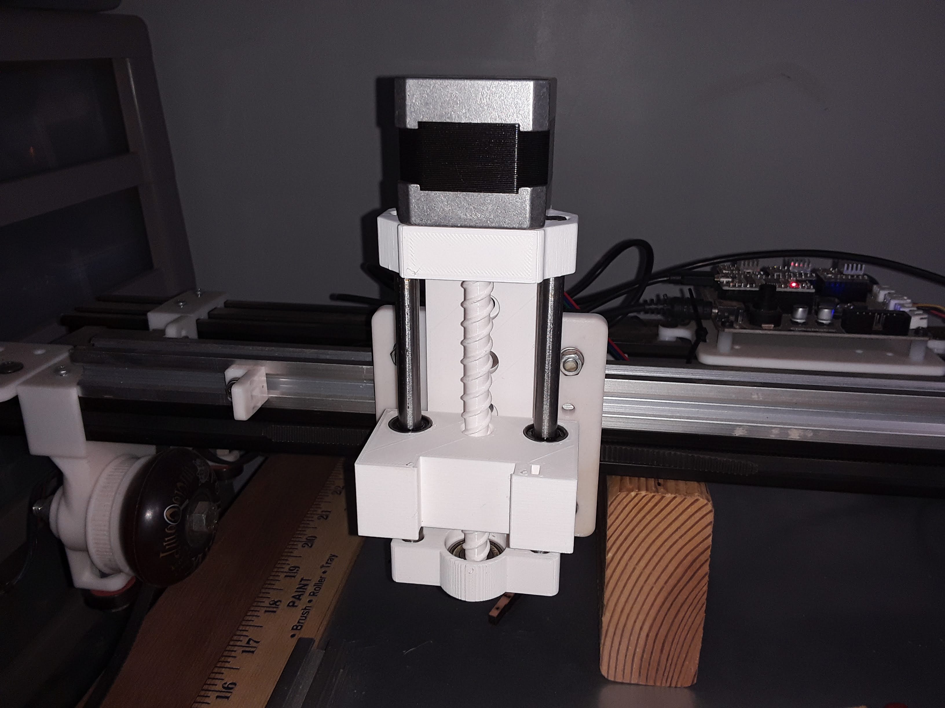
I 3D printed David’s original mount intending to use it, but I found some slop in the plate. I did not want that to translate into laser engraving artifacts, so I ended up rolling my own simple mount. I suspect the slop will be there for some 3D printers and not others, and I could have just scaled/modified the slide to solve the problem, but if you are looking for a universal design, then you are going to want to figure out some way to either lock the slide or to add tension to the slide.
I believe David’s new design with the slide and locking knob solves this slop problem.
I just used some strips of aluminum tape on the rail portion of the carriage to take up the slop. It took a couple layers but now it doesn’t move at all but still slides.
I printed out the parts yesterday. I used different colors for most of the parts mostly to use up the end of some rolls of filament. It came out pretty good but do have a little slop in the 2 side rails. I did test prints on this & was too tight if I used a closer tolerance. My printer does not seem to print as good a tolerance as it used to.
The sloppy fit might be that I used VoxelPLA for the blue parts & the other parts I used eSun PLA+. I might do a tolerance fit print using just that plastic & see if I can get a tighter fit. I decided to try a couple of rolls of that filament after seeing a couple of Youtubers mention. It prints really nice & only $17 a roll with free shiping for 2 rolls. Looking at the data sheet compared to eSun, looks like it will have more flex to it, but feels pretty strong. Here is the link to their site. VOXELPLA - Most Reliable PLA Filament 1.75mm 3D Printing for $16.99
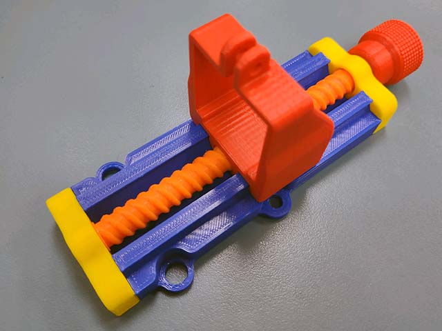
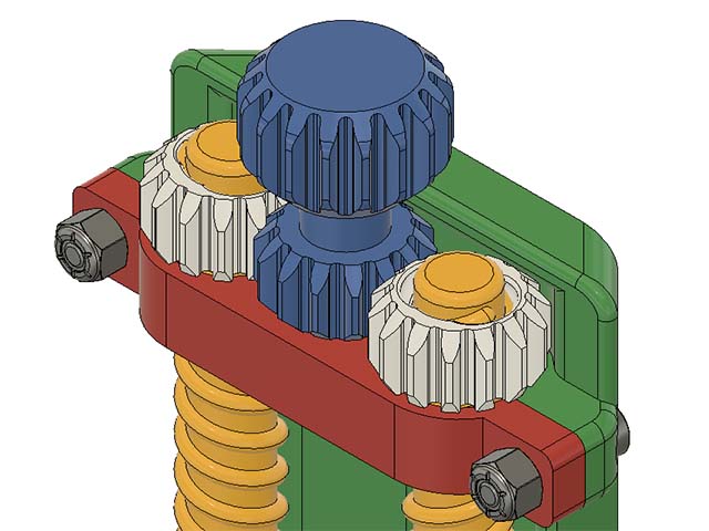
Since the threading on this really feels snug, but moves easily, I am looking at using 2 threaded rods with a gear driving both in the middle like this design. Yet ANOTHER Machine Vise by TheGoofy - Thingiverse
Funny! That “Yet Another Machine Vise” could almost be used "as is" for a Z-lift machanism…
Speaking of filament… like you, I’ve recently felt that my 3d prints were not as good as before. But I’ve also noticed that the same Sunlu PLA I’ve been using for several years has had a tendency to get really brittle over the past several months… the humidity, I suppose. But I just put on a new roll, fresh out of the box, and the prints seen much improved already… and the filament, right now, is nice and flexible.
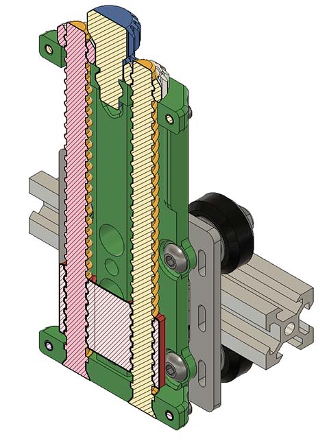
Getting a nice dovetail with the carriage cross section formed in the xy is a challenge, but those threads would be hard to print well in any other orientation. If movement can’t be eliminated with better prints, maybe adding a way to lock the rails would be worth it. A setscrew would be no fun long term… something quick release would be cool (print in place cam lever or similar).
@dkj4linux, if you end up with too many rolls that don’t print well, a modified dehydrator or over the counter filament dryer can bring them back to life. PLA isn’t the worst with gaining water, but it can go bad that way.
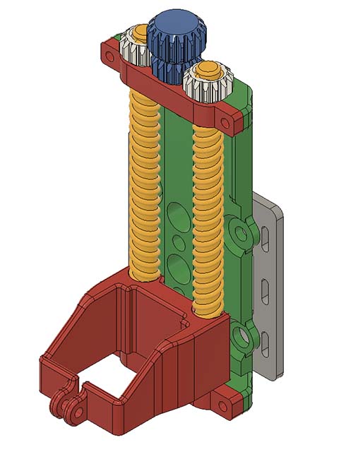
Making some progress on this. I have a little more tweaking before I will be ready to print it. I am trying to get as big a bottom footprint for the threaded shaft as possible, so I want to adjust that a little more. I also had to cut the threading out of the 8mm top bracket, but looking at it again, I should have enough room to cut a bigger hole in there to allow for the treading to go thru it.
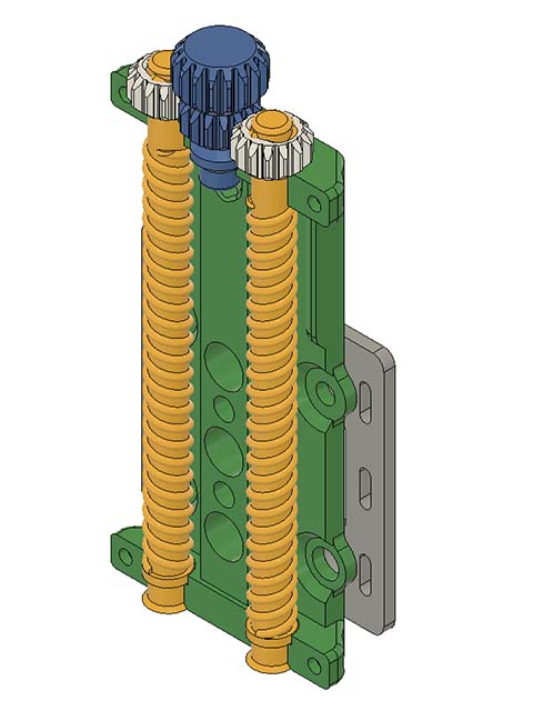
I have it close to test print time. The mount is only 2mm below the metal Gantry now. I opened up holes at top so the threads can be continuous. I originally was putting threads int the top part & then realized it would not turn if I did that. At least I figured that out before printing. I am trying to decide whether I need to constrain those gears at the top. While editing this message, I added a little channel at the top of the green part so at least they won’t pop out easily.
It looks like you have the threads mirrored for the adjustment mechanism, but with the center gear like that, both screws will rotate in the same direction, so it will not be possible for it to move.
You either need to have the gears on the screws directly mesh with each other, or have both screws the same direction thread.
Of the two, I would probably choose the former, as it simplifies construction, eliminating one rotating axis, and just put the hand knob on top of one of the screws.
Thanks for the comment. I missed the mirroring, luckily that is only on the assembly & not the original print file but will correct that in the assembly.