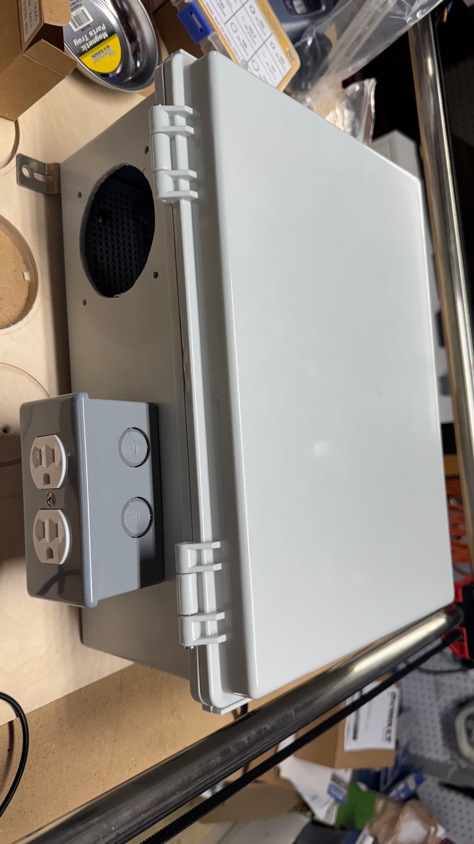
Making progress. Wired up the line input to the PSU and relay and receptacle. Decided to splurge and got the Leviton lever receptacle…SO easy to install. Receptacle is mounted outside the main enclosure, for additional safety, though with the lever wiring on the receptacle, there’s no exposed terminals anyway.
Still need to wire up the low-voltage side of the SSR, but I wanted to make sure I do that right so I don’t screw something up on the board. From what I’ve gathered, it looks like the 5V capable GPIOs to the left of the endstop pins is the right place to wire up the SSR.
[EDIT]: Turns out that the default firmware already has macros wired up for GPIO 26 and 27, so this is much easier than I was expecting. I need to check the underlying gcode for the macros so I know how to turn the tool on as part of a job, but I wired it all up and it’s working perfectly.
Also found this thread that indicates that I could also use the MOSFET terminals, with a helpful video by @Nathan_Doty (Thanks!). I think I’m going to try with the 5v terminals first, however.
Pics:
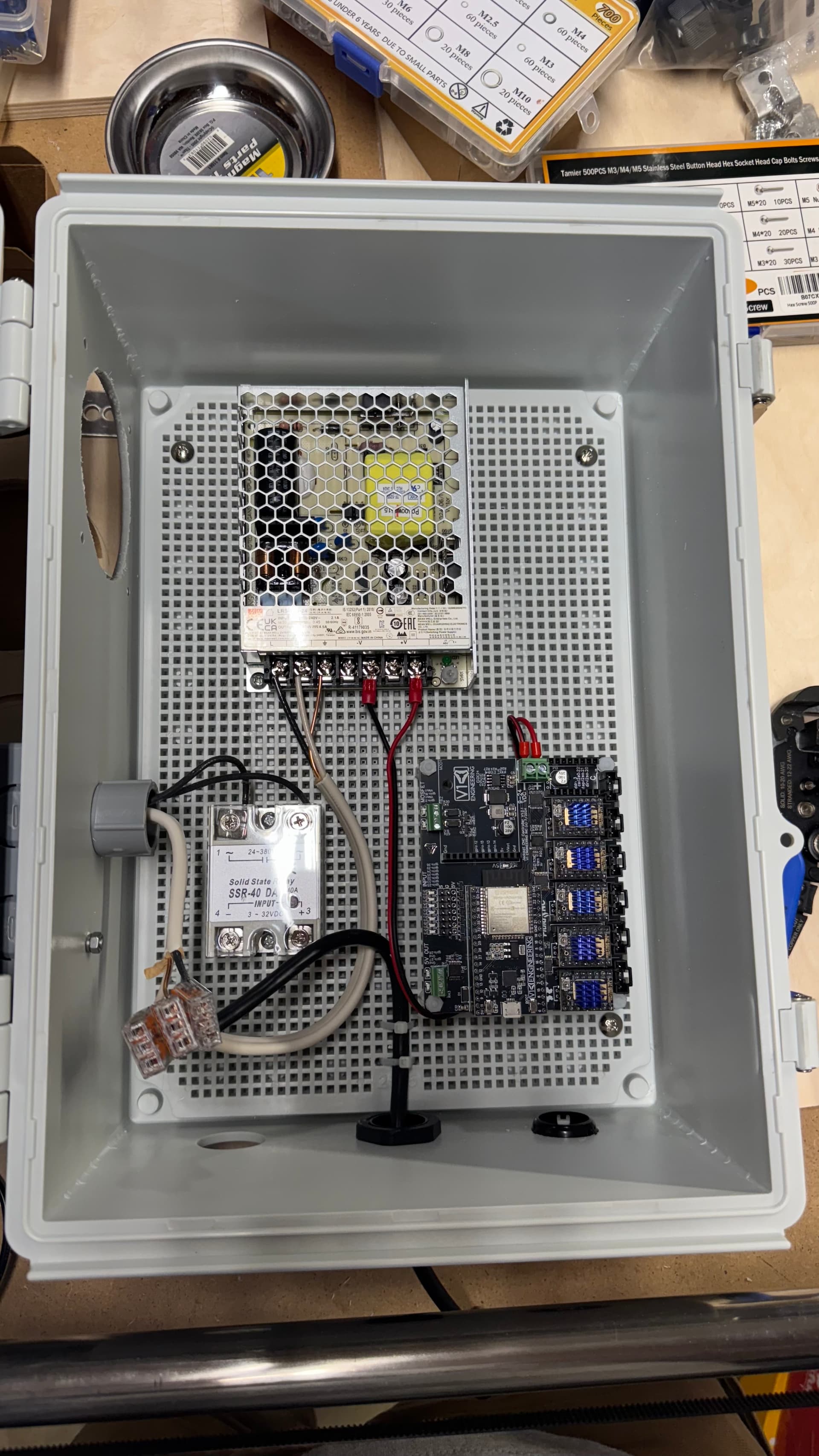
Fan (24V) will get wired to the spare terminals on the PSU, but I’m waiting on longer bolts to mount that.
One last thing…I see from this post (and saw on the video mentioned above) that some folks use a heatsink on the SSR…should I be planning around that? Currently, the SSR is just mounted to the plastic mounting board. Would rather not melt that, or risk a fire.