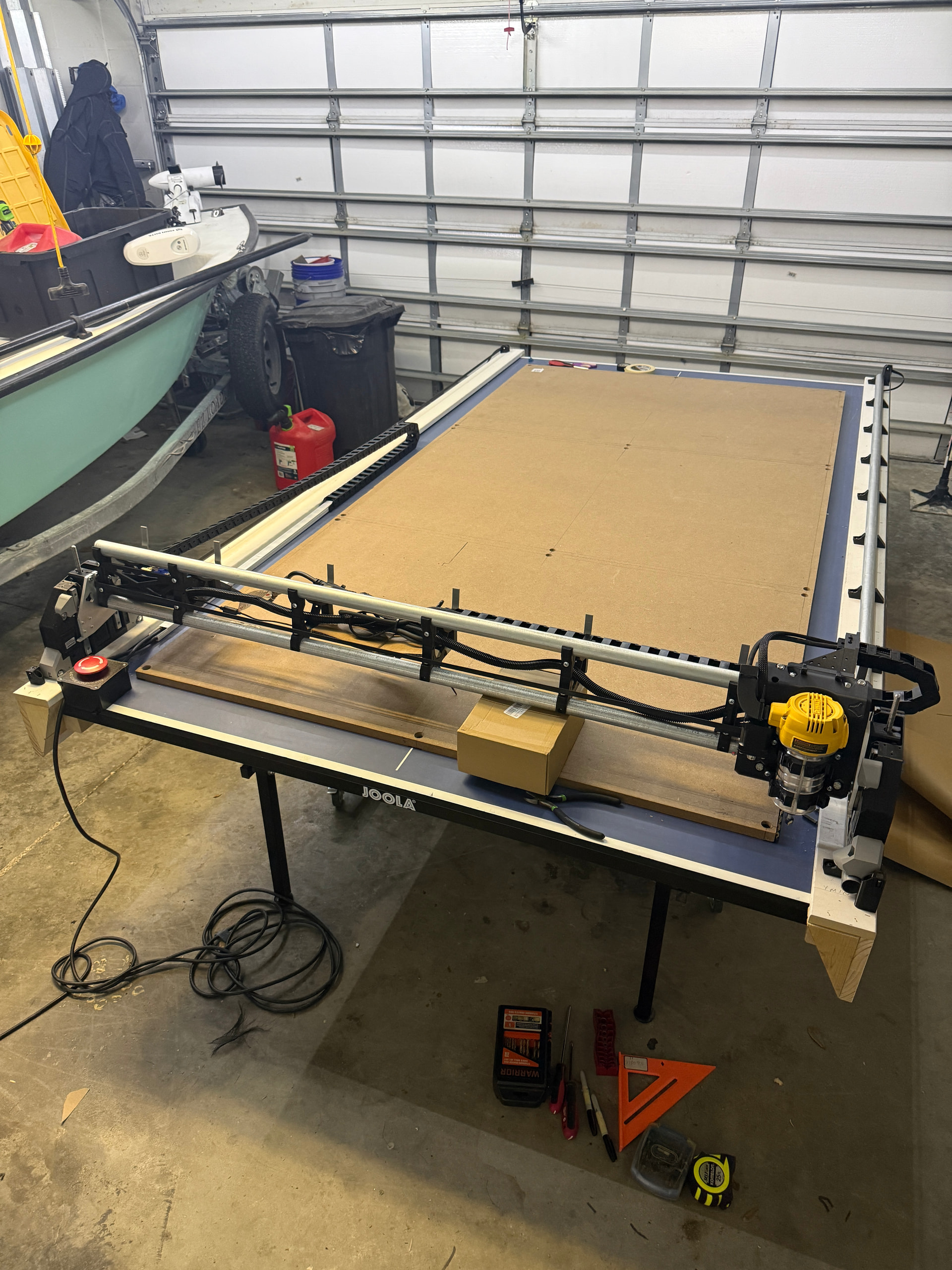
Here is my Low Rider v4 Build!
I run my business from my home so space fills up quickly. The humidity can also be an issue in Florida with a hot garage, so storing in the garage, fully set up was not an option. This allows for me to store it all in the house, temperature controlled, for most of its life when not being used. Sets up and tears down in about 20 mins or so.
It’s been about 10 months in progress; building the machine and developing how the table would function and be built. After seeing other builds really leaning into the portability of this machine, I prioritized being able to set it up and take it down so that I do not have to give up any garage space and still maintain full 4’x8’ cutting area was a huge priority. I primarily use it to contour cut signs with 1/8’ thick materials like dibond (max metal, ACM) but if we are building the dang thing I wanted to be able to ‘grow’ into it….cut thicker materials down the road, mill some thick HDU foam signage, or even surface large live edge slabs possibly…..So it has a cuttable reach of just about 48”x96” and the Z depth can be adjusted to up to 3.75” thick. The rails discussed below have multiple height positions in which they can be bolted to the ping pong table (support blocks with dimensional lumber go under the rails and on the table like risers). I can incrementally add 2x4s and 1x3 lumber to add rise to the rails. This essentially creates a “drop table”, but instead of dropping the table surface, the rails get raised. Again, not something I will use all the time, but definitely something I will explore at some point. Here is the information I have to share about my build. Definitely had my share of setbacks and puzzling/frustrating moments…..but this forum and YouTube builds have been so helpful during my progress, I wanted to share with and help others.
Ping Pong Table was bought used and is 61”x108”….folds away in two halves. I added 2x4 “edges” with countersunk 1/4x20 threaded inserts. The 2x4s actually were flush with the bottom plane of the ping pong table but did require an additional layer (from the face to the outside of the table edge) to be flush with the outside edge of the actual edge of the table. This allows for the rails to be bolted securely. I did add about x4 tabletop “leaf” latches that are screwed to the underside of the ping pong table and draw the two halves together. These clasps are adjustable. Bought on Amazon. I added bigger (in diameter) height adjusting feet on the legs for a better base that is adjustable if need be. Those were bought off amazon.
It has two removable “rails” that bolt to the sides of the table using 1/4x20 bolts that pass through the rails and into the 2x4s and 1x3 lumber that have been added to the edges of the table. The rails that sit on the table are 1x6s and 1x4’s…one piece……connected with brad nails……with multiple holes drilled for varying heights of the rails. Pieces of “2 by” and “1 by” lumber get stacked between rail and table surface when I want the rails raised (this allows for more Z travel and can accommodate thicker materials). The rails are one piece and also lock the two table halves in tightly pretty well when bolted tightly. One wood rail has the conduit rail attached and both wood rails have the 3d printed end stops/belt end holders attached. I store these both wood rails inside, on 2x4s, that are screwed to a wall, in the house…each rail is supported across its entire length.
The spoilboard is a full 4’x8’ sheet of 3/4” MDF cut into three pieces so that its weight is manageable….(a full sheet is so heavy! and will buckle the ping pong table). These three peices get attached to the ping pong table surface with 1/4x20 bolts and threaded inserts (embedded into the ping pong table surface). The bolts attaching the spoil board to the ping pong table have to be countersunk and can be milled right over. The bolts and threaded inserts were all bout on amazon. The spoil board surface (if huge adjustments are needed) can be leveled by placing a few washers under the end or side that needs to be raised (between the table and spoil board underside). I am still working this out…seems like my initial surfacing is not completely level or true….but definitely good enough for full cut through passes.
I did add drag chains for both the y and x axises. These were purchased from amazon. The y axis drag chain is connected to actual table top with zip tie tie during set up and then is cut away each time during break down..cables along y axis in drag chain are concealed in snap and go white concealing ‘tube’ bought from amazon at the end of length. The other end is permanently ziptied to the bottom of the control board (strut plate under control board). The y axis drag chain carries the extension cord for the router and cnc machine. The cnc and router both get plugged in to a double outlet extension cable. This dbl extension cable gets plugs into an emgemcy stop “pigtail” plug. This e stop pigtail plug runs the length of the table into a big red e stop button. This kills power for both the cnc machine computer power and the router. This is definitely delayed a little…estop is hit…. and the computer is killed while the router (still spinning) drives into spoilboard). not perfect but close. The e stop was bought from amazon.
I think this pretty much covers my build process and setup. Since these pictures, I have cut 10mm ACM as struts plates and installed them (two of them following the directions on the website)….even after following build directions completely, I did end up one 3d printed strut support support short…..I was able to 3D print the support no problem, but it was a surprise that I needed an additional after following all the directions…I had the notch for it in the actual strut plates using the calculator provided, just needed to 3d print another support for some reason…I did have to 3d print some parts and also some that I found useful from other YouTube videos….the resting blocks (when machine is powered off…x gantry wants to lower automatically under weight). I did 3d print the reroute for the dewalt 611 router wire…with installed, it routs wire upwards rather than sideways (bumping into leftmost x axis).
.If you have any questions at all, just reach out….I am happy to help! cjfabes8@gmail.com. Just for the record, I bought all the 3d printed parts along with the jackpot 3 controller. I have a Prussa mk3s 3d printer…but did order the kit and everything else printed/included already. I do have more pictures of build and finished machine, but it did not let me post them all as a ‘first time’ user?…holler if you wanna see more!