No. It’s not even done, AFAIK. So there aren’t any tutorials.
I’m hopefully going to give this a crack once my parts arrive - I got all excited when I saw there was a new post!
I’ve started some tests now that I received my IR diode pairs, bu unfortunately have troubles getting reliable “low speed” measurements : it seems I pick-up many superfluous “turns” so… bad measures.
Note that I tried at first on an Arduino UNO, and it was better, but switched to a Nano, and the problem is far worst. I’ll have to find out what’s happening… (Ordered a low cost ascilloscope, but need to wait a few weeks… will keep going in the meantime)
Since I’m too bad an electronician, I don’t now how to rig the correct input filter (I suppose a resistor/capacitor pair should do the trick, but what values for them ?), so will probably test with getting analog measures and filter them on the software side.
I also checked on my chinese 500W spindle’s PSU, and was prepared to reproduce Christian’s (ESTLCAM) electronic circuit to replace the speed pot with it, but measured that the input wasn’t 10V but 3V max.
I used the left part of the circuit (resistor +capacitor) to get a filtered command from the PWM output (0-5v), but will need to get that down to 0-3v
Once that’s done, I should be able to “command” the spindle, and measure it’s speed… and it’ll be time to insert the PID as Ryan did.
And then it’ll be time to see on the CNC firmware what GCODE is best , and how best to forward it to the “PID controller” (a 255 steps PWM seems too lossy, perhaps use a “servo” signal" with its greater precision, or even an digital/serial transmission?)
Lastly, check how / if it’s possible to get ESTLCam to generate the gcode for the spin RPM…
(That’s if I don’t switch to other projects in the meantime…)
That is why for now I am using the PCB mounted pair and the encoder disk. I am trying with the cleanest signal possible, then I will try and work out a smaller solution. The disk seems to give extremely consistent numbers, so I feel I have a baseline for ideal. Some sort of filtering/averaging will probably need to be added for the reflective sensors.
I have a bit of a cold, so I might work on this today, I had planned on getting the toolbox build dirty but I think it will have to wait.
Since I last posted I have an LCD working as well, and I think Heffe figured out my variable rounding issue. So as of now I can either refine the PID or integrate the LCD (or change to the oled).
If i wanted to use the AC dimmer module to control the speed of the spindle where would I pick up the 5v signal from the RAMBO board. I was looking at using FAN2, but it is 12V.
If you use marlin 2.0 there is a definable pin for speed/laser control. You pick the pin you want from the rambo wiki. Pretty sure in this thread I have pics and details of what I used.
Has it possibly got something to do with the timing of the microcontroller?
I’m looking at speed control for a record player and people are suggesting i use something like this http://esp32.net/#Features instead of an arduino due to the arduino having a low resolution/clockspeed
I’ve got it ! Added a smallish capacitor (.75nF) between the IR receiver “signal” and ground, and if works flawlessly.
No need to add an encoder ring anymore, the solution works really well.
I’ll just update the code to try and get better reactivity by just computing frequency as inverse of time between two detections rather than counting the revolutions between two periodic updates (at which partial revolutions can have some impact).
I thought Ryan’s code already does that? Are you using his interrupts and everything?
Yes, indeed, Ryan’s code does just that (as I mentionned in a message that I mis-edited/deleted), but since I had troubles, I tried a few code changes/iterations before testing a “hardware” modification, especially since I don’t use (yet) the PID controller.
Now that I have “feedback”, I should be able to switch to the “control” side of things. (Tomorrow ?)
BTW, any thoughts on the 255 steps “resolution” for command ? Is it precise enough ?
WRT Ryan’s code, now that I look at it more closely, wouldn’t it make more sense to have the PID work on RPMs rather than % of the max input ? Especially with the “discretized” input value, which could cause problems with big speed steps.
I’d suggest to convert the target PWM to a target RPM and use that as the setpoint, use the computed “optical” RPM as the input, and convert the output to PWM just before control of the hardware.
(But what I know of PIDs, I read on th Internet, so may be completely wrong)
Oh, and here are two pictures of the sensor and the mount I “designed” for it under the spindle : first is “unmounted”, second is near the “spinning” collet.
[attachment file=“58241”]
[attachment file=“58242”]


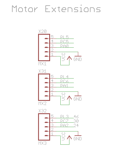
I would like to check with you before I go and start playing with the board that I am getting the correct pins. After going back threw the thread, I see that you are calling to use pins 45, 31, and 32.
Rambo pins-
#define SPINDLE_LASER_PWM_PIN 45 // MUST BE HARDWARE PWM
#define SPINDLE_LASER_ENABLE_PIN 31 // Pin should have a pullup!
#define SPINDLE_DIR_PIN 32
I then see that in the RAMNo manual on page 64 that Arduino digital pin 45 is PL4 and pin 31 is PC6 both on Motor extension MX2 (X31). The other pin Arduino digital pin 31 is PC5 and is on MX1 (X20). Is this correct or am I reading things wrong.
Thanks for the help.
1 Like

I had a second ground on the motor header…not sure why. You can use those three. I am flashing and plugging everything in again.
1 Like
thesfreader Do you have some links to the hardware you are using for the leds and sensors, or are those the ones I linked? I am beginning to think smaller size or even surface mount would be a better idea if we are going to point it at the fan or inside at the shaft.
At it’s coarsest it gives us 118RPM between steps. I think I am happy with that, I would actually be happy for it to oscillate between two to keep harmonic chatter down. In reality we can’t operate below 30-50% max RPM speed so scaling that will almost double that to 60RPM between steps…I would be stoked at this as well.
I will double check but this is to allow for some filtering and scaling depending on the strength of the input signal, later on.
I don’t understand the difference. In the program this is just the other end of an equation, I use it before any rounding might occur. Trying to work with the purest data.
I have not touched this in a while, I am flashing right now. This is all very early and I learn and have to learn a lot every time I touch it. I spent a day with a weird “C” math issue that Heffe understood quickly and I could not wrap my head around for a whole day. RPMMATH was rounding to 0, because of the variable placement, some sort of overflow. Physical damage was done, I had to take a break to get ready for MRRF. Hopefully now with fresh eyes and a few more hours into this I/we will see a bit more structure so far so good though.
Also with a few of you playing with this now we can validate the program instead of just going on my word.
Update, finally.
Got it setup and running again. Took me a while to get comfortable with the code again. Fixed the zero RPM issue, so now it show zero (eventually) and this will clear the PID. Previously it could just get stuck on an RPM value in the thousands so when restating the PID loop it would jump. Updated GitHub.
The PID needs tuning but I am not sure auto tune is the best way to do it now. I don’t know how user friendly it could be, seems you almost might have to know what your doing to set it so that eliminates beginners. I will try and figure it out again, and I also got another round of manual tuning in using the serial plotter instead of the serial monitor. I didn’t even know that existed. Probably as good as it gets until cutting is involved.
Actually, no, I used some from aliexpress. As for the type size/surface mount, it’ll prpobably depend on the router/spindle used. I’ll be happy with “my” solution at first, but I suppose on the Dewalt it’s quite different.
Oh, yeah, hadn’t realised that it was this “close”. You’re right, precision seems enough as it stands…
Still, I think it would be good if we could transfer directly RPMs via GCode commands to marlin and from marlin to the speed controller (perhaps via serial or I2C ) and then have the speed controller adapt that to command the output. That way, no “calibration” needed on CAM or marlin side to convert the speed to PWM… (also will have to check how the CAM translates RPMs to gcode…)
(speaking of serial/I2C commands, I also would like to create a small “joystick” controller that would send commands via this link to marlin, to ease jogging for example. Seems easy enough (if a lot of work).
Actually, I don’t think it works on the Strength of the signal, since you only get “binary” edges (raising/falling/up/down). Filtering, I gues you can do, but on the “sampled result”.
Yep. dépends on what you choose as “pure” data. My POV is that the effective RPM is the most pure as the better connected to the physical reality but also the most precise. But if you use the “coarseness” of the PWM as a feature to keep harmonics down, that’s a good point too.
I’m stuck for now at that point where I should be ready to connect the RAMPS output to the spindle control, and hope I avoid physical damage… Probably will wait for my next week’s vacations return to test that.
Yep, that’s what I’m planning to do ! ![]()
We already do. M3 S8000 is rotate (clockwise) at 8000 RPM. We only talk to the marlin control board. The nano is just controlling the speed, manual (outside of Marlin speed control is also possible).
Different project and there already are a few. Pointless with work offsets and dual endstops.
Are you looking at the code I have on github or the screen shot I put up here from day one?
Again, maybe you are looking at the wrong project version. We read the direct data from the leds (sensor) and from the arduino PWM output. PWM is just the way the way marlin talks to the speed control, I guess maybe you are asking why marlin is not just passing the direct command over (M3 S8000)? Maybe it can, I know I do not want to money with marlin too much. If this works and there is a need for it I can see if it is possible but really the sensor data I get seems to be at least 100RPM “dirty” or the spindle RPM just isn’t as stable as you would imagine.
Well hopefully in a few days I will have tried this out in the real world.
After sleeping on it I think I might be going about this wrong. I think simply setting two PID values is the better way to do this.
1-A soft start for the initial turn on, so lower P and I terms.
2-Running more aggressive terms for a faster response.
Right now I keep trying to tune the turn on curve (eg zero to ~9500RPM) and that make the small jumps and disturbances suffer (eg 9000-10000)
The way I’ve solved that in the past is to leave the pid aggressive, but add in a Target rpm that changes smoothly. So if your target was 0 RPM and you received a command for 10,000 RPM. You would change the input to the PID with a certain RPMs/sec. Sort of like acceleration in Marlin.
Just be sure you change the target based on the previous target, not the actual RPM, so you lead the controller.