That library has an auto tune available, I started to look into it but since I had a working machine and it did not seem dead simple I left it as is. If you could get the auto tune running that would be awesome!
Sure, I can look into that. 
I am more of a .Net developer but, I have done a fair amount of Arduino fiddling.
1 Like
Dont know if y’all have thought about this, but can a feed-forward be used in this case in order to account for an expected load? Then your PID values would correct accordingly. People use feed-forward in PID loops all the time, and it is especially effective in velocity control (as we are doing in this case). Basically, it just adds on a certain amount proportional to your set point. I have some experience with this through FRC Robotics, and there is a little blip about it here.
1 Like
I really do not have much experience with real world PID tuning. For that to work wouldn’t we need to be able to input when it is under load and what kind of load (wood/metal, finishing pass/slotting)?
I did the initial tuning in free air just to error check and see how it worked, but if you always cut wood I am confident you could alter the settings a bit to have better performance in that material.
As it is now it is pretty amazing so if it could get better that would be awesome. I have unplugged mine for now though. The 611 and makita speed control that are built in seem to actually do a decent job.
Perhaps I need to purchase one of the PID boards and try my hand with it. The feedforward in this case would account for friction within the motor with regular load. With FRC Robotics, the regular load would just be friction within the drive train and with the floor. Unexpected load would then be accounted for with the P, I, and D values. So I guess in this case, regular load would be free spin (so it would account for friction within the router), and unexpected load would be whenever you start actually cutting.
The speed controller does not have the gcode information. So it doesn’t know how fast the bit is moving through the material, or if it is even moving. Marlin doesn’t really even know how much material is supposed to getting removed. For example, it doesn’t know the difference between a full depth finishing pass, and a slot cut, or a 10% stepover cut.
Luckily, I don’t think the problem is that hard. A little overshoot, or steady state error is still going to be better than nothing, and nothing works pretty well as-is.
As I’ve said, chasing 0’s (or perfection in any of its myriad forms) is the path to madness; and while it’s an interesting thought problem, I hope nobody thinks it’s anything anyone needs to do. Except you in the corner mirror, you OCD/ADD freak…
1 Like
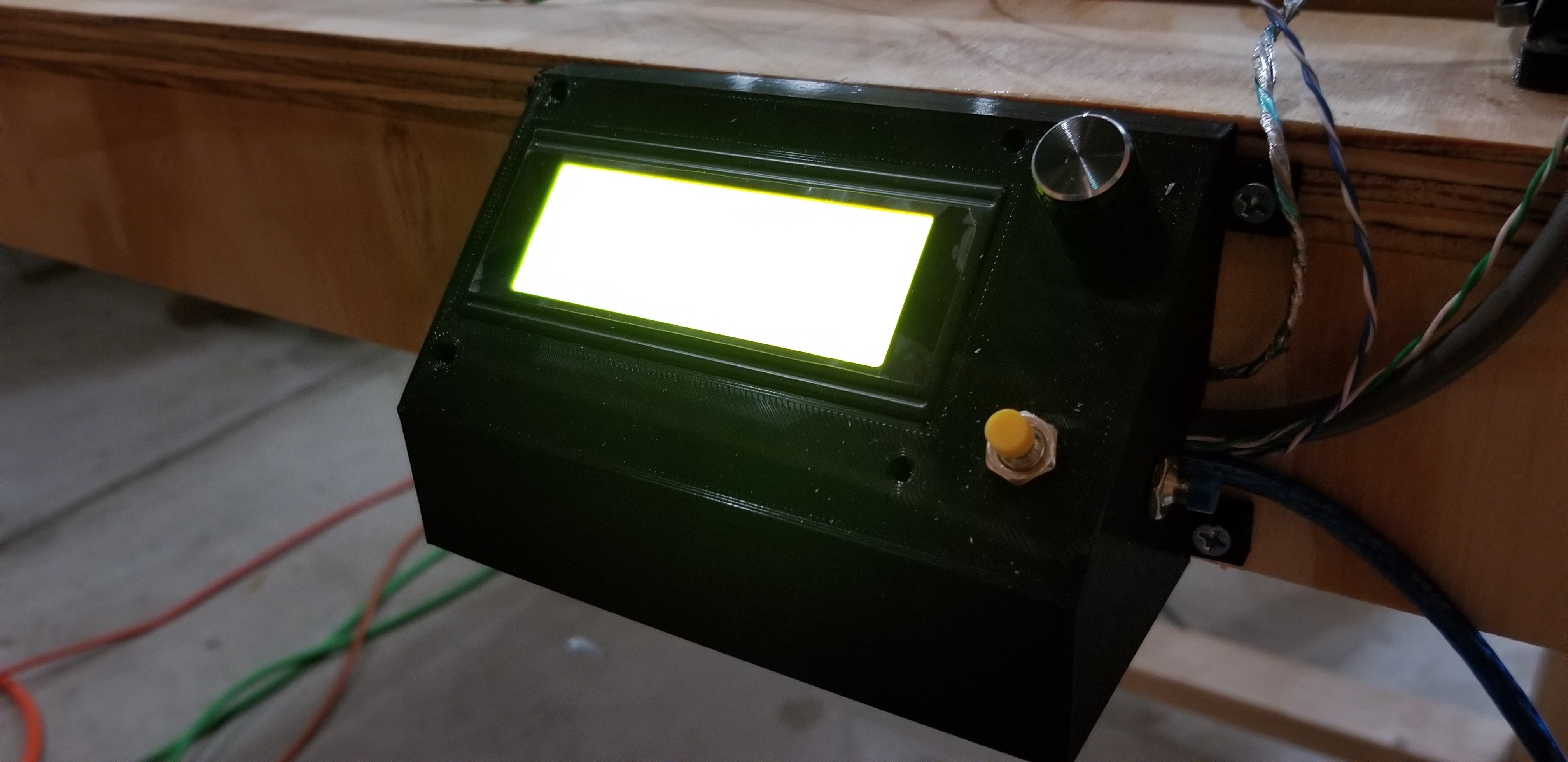
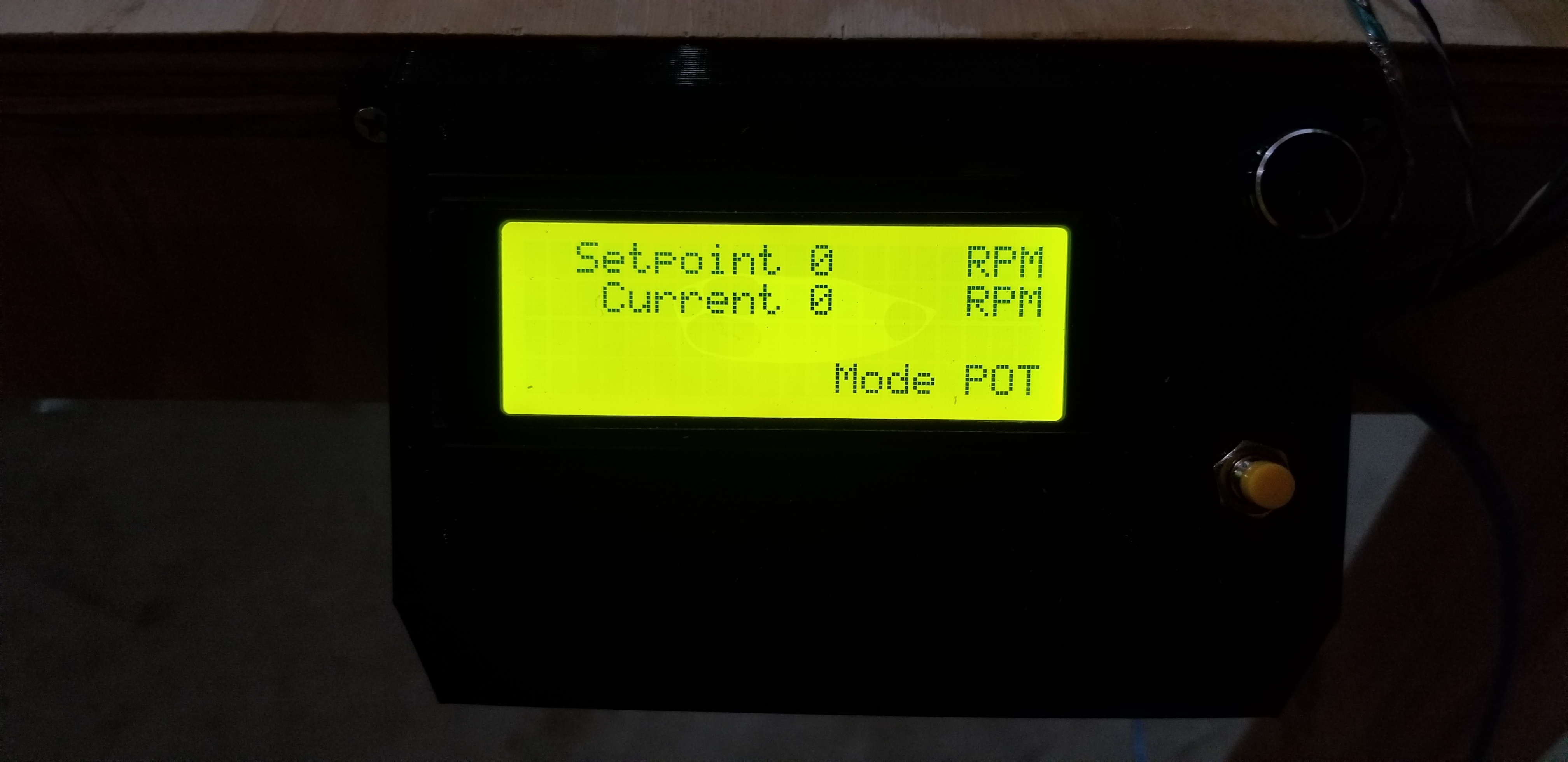
Would just like to share progress on my PID install!
Having a lot of fun with this thing. Added ability to switch from Off, to Potentiometer input, to Marlin input. Still a work in progress, especially with finishing up the look of the LCD.
Side button will switch input modes.
Front button will read and update potentiometer reading. This way you can accidentally turn the knob and eliminates any noise issues.
6 Likes
Heck yes!
Are you using the nano circuit board yhats no longer available in the V1 store? Ive just received the developer kit and wondering if i should get one made.
I made one on perf board. I needed additional inputs for the buttons and the POT anyhow.
Thanks.
Are you posting the software somewhere? Looks great.
Thanks!
I was planning to finish tweaking and working out any bugs but I can share it as is if you’d like. I’m far from a professional coder so its definitely not pretty.
2 Likes
Sounds good to me. Just don’t forget. I frequently think, “I’ll just do one more thing” and them lose track and never share. Someone has to be really rude to criticize open software (they will be rude, but you can ignore them).
How critical is it to include a screen in the PID itself? I’m planning to use a grbl cnc shield and the V1pi image to run the MPCNC. Will that allow me to display actual rpms through the browser interface?
Not the actual rpms, but I think it shows the set point.
I’ve never messed with a pi or V1Pi but would it be possible to send a pwm pulse from nano to one if the Pi’s gpio pins and display the value?
Edit: using a level shifter or voltage divider to get from 5v to 3.3v as well.
You can. For sure. But a simpler solution is to just connect the pi to the usb, and read from the serial port.
The hard part for octoprint or cncjs, is displaying the value. You can do that too (it is open source), but in some ways cncjs is much more complicated than arduino.
1 Like
Is the sensor holder for inside the DW660 linked in this thread anywhere? I can’t seem to find it, and that’s my next step.
Thanks!