Hey all - I realize this request for help may seem to be coming from left-field, but of the forums I follow I feel like this one probably has the most folks that may have appropriate experience to offer some reasonable suggestions…
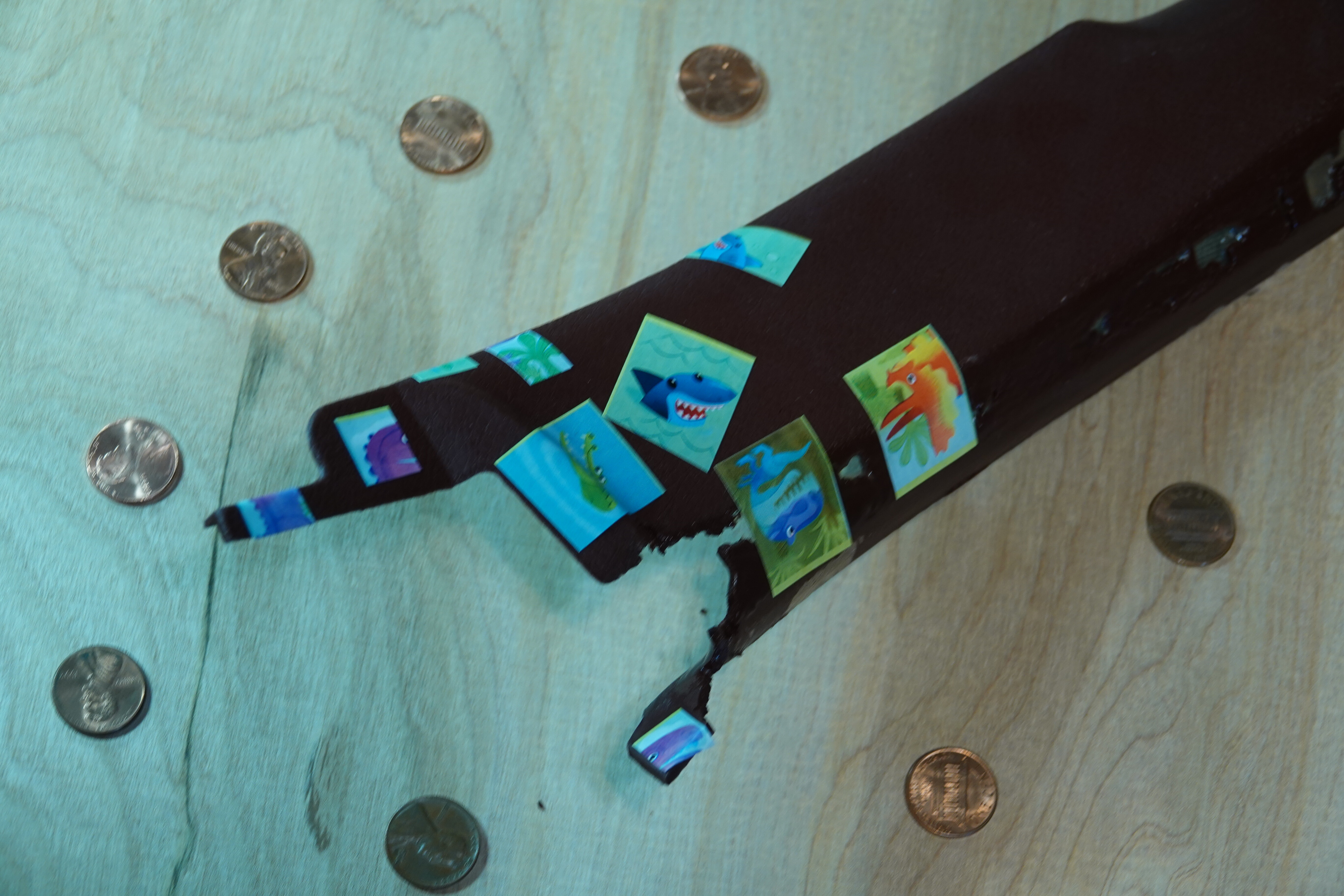
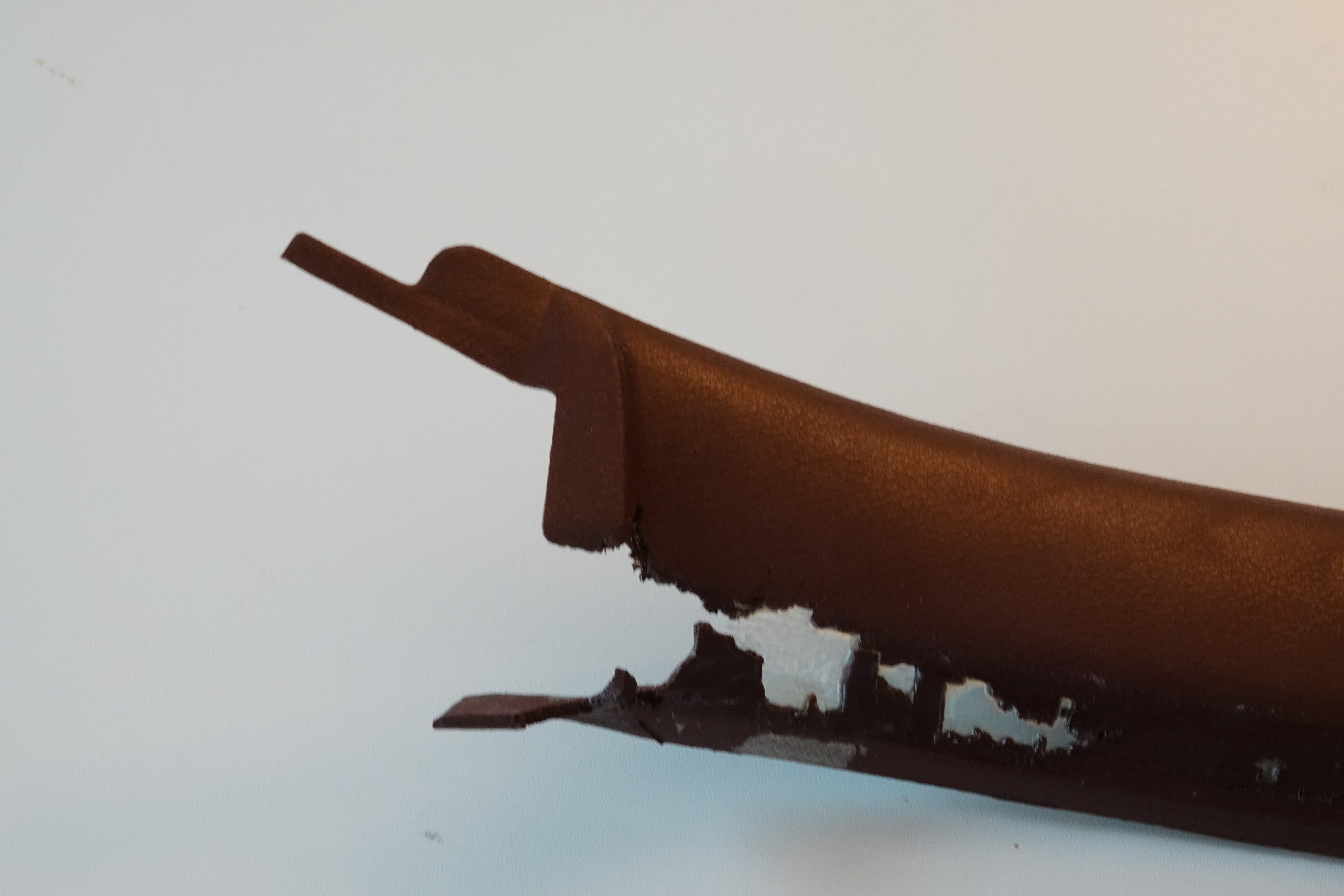
I’m trying to create a 3D model of a piece of interior trim from an '83 Rx7:
As you can see, the original part is quite far gone. My goal is to create a reasonably close 3D model of this existing part, take that into meshroom (or fusion) to sculpt the missing bits, then use fusion to create a reverse mold of the part that I can set the original part into and fill in the missing bits with fiberglass…
I’ve tried several different photogrammetry apps to create the original model, none have been even close to successful. Most recently I tried ColMap and 3DF Zephyr Free. Prior to that I tried several different iPhone apps (don’t recall which at the moment).
All of the apps I’ve tried seem to fail miserably. So - any suggestions on how to get this puppy modelled?
BTW - the original part has quite a few compound/complex curves and I’m not skilled enough in the “form” bits of fusion to model it directly…
It might be helpful to change the lighting around the part a bit. Those photogrammetry apps infer a lot based on highlights and shadows, so aiming lamps from a variety of angles to get as “flat” an illumination as possible, along with as regular a background as you can manage, may help.
Do you know anyone with a 3D scanner? I’m guessing the part is a little big to get on the Thingiverse-sized turntables I’ve seen.
I haven’t done much with photogrammetry, but that even-ish color with few distinguishing features doesn’t help the algorithms “see” the surface, I bought some thin tape in multiple colors to put all sorts of random lines on a similarly smooth uniformly colored piece. The project was abandoned, but I bought this set https://www.amazon.com/gp/product/B075NZ1S9C to do so. You could also draw lots of lines with a white paint pen or some such too maybe - anyway - give it more things to “look at” someway perhaps.
This video came across my feed last week and might have something to offer. He is essentially doing the same thing you are trying to recreate a car part that is no longer available. My takeaways were that he got decent results using the Creality CR-T scanner, and that the spray makes a big difference.
I’ve had to do something similar to what you are doing once. I’m terrible at seeing any kind of “organic” shape in the real world and being able to model it, and the part I had to model needed to be functional as well. I used the Qlone smart phone app. The results were not great, but the app is free, and, at the time, it was only a $1 USD to get the 3D model from the scan, so I got to skip past all the work turning a point cloud into a 3D model. I couldn’t use the model directly to make the part, but it made a great reference in Fusion 360. I was able to model around the STL file to produce the part I needed. It still took a few 3D prints to get the part right, but I wouldn’t have been able to model it without the scan.
Not photogrammetry, but 3d scanning with the iphone infra red camera (any one with face recognition) I’ve had success with EM3D it’s free to muck around with - you pay if you want to use a scan.
You are using the rear facing camera so it’s a bit tricky - but you can either print a mirror that clips to the phone so you can see what you are doing or easier if you can borrow a phone is to use tha app to link to the other phone. That way you can use it back to back as a view finder.
Lighting is all as @ttraband has said - and with panels which are similarly coloured if you stick a bunch of little dots on them for the camera to register on that will help as well.
This is all based on my experience writing computer vision algorithms. I haven’t actually used any of the commercial offerings.
I agree that markers, tape, or stickers might help. Some software might also have trouble with the many many features in the rotted out area. That area has a lot of detail that isn’t very unique and can morph a lot with small angle changes.
The way these things work is trying to match a “feature” in one image to the other. The distance these features move (in pixel space) determines the depth from the camera. “Features” are things like the corner between a light and dark region.
If you had a bunch of cartoon stickers, you could put them all over. The features it would find would be very unique and easy to track. Then take photos that are pretty close to each other (less than 5 degrees and a few inches apart). That will help the software match features from the two photos and track them through a bunch of photos.
Good, even lighting is important, because there are a lot of false features from shadows. Two or three lamps in the room, far enough away, should give you good lighting, I think.
You could also try to cover the rotten area with some tape. The tape would hide those very fine features that may be confusing. As a bonus, it might make the final modeling easier.
I am curious to see how it goes. No matter what, I would expect it to be pretty rough.
@jeffeb3 I definitely like the stickers idea This will probably be what I attempt next…
@bitingmidge I’m not certain whether I tried EM3D or not when I was trying out the iphone apps. I did try a couple that used the “face recognition” (IR dot) camera to do the scanning. Those apps did give me a fairly dense pint cloud, but I had a lot of issues with meshlab trying to turn it into a usable solid (lots of flipped normals, etc)…
The backside of this part is fairly complex and I know when I was attempting this before that I was trying to capture that side as well – which I’m sure didn’t help. I’ve since realized I don’t really need the back side, only the ‘front’, to accomplish my goal…
@Tuco I had considered putting dots on the surface, but it seems like that could hurt rather than help. The suggestion to use colored tape seems like a good one - but I think Jeff’s suggestion of stickers is probably the winner here.
Thanks all for the suggestions! I’m going to give the stickers a shot and will definitely report back on how it works out.
It seems to be the same part you can find below with pictures then maybe it would be easier to design it from scratch from pictures.
I’ve never done that before but from what i have seen in Fusion360 tutorials, for reproducing a part skilled people would do something like that:
If your other side trim is intact take it as reference as it is just same mirrored part and shoot it with your camera to have top, bottom, front, back, left and right views.
Insert views/pictures in Fusion by using Insert Canva and place them on correct axis.
You need to know correct dimension for beeing able to scale imported pictures in Fusion360(or other soft), use caliper or ruler to mesure your parts and scale your images accordingly.
Then make a sketch over each picture and trace each coutours(LightBurn Trace image function could also help getting key points/line of the shape you can the export to SVG and import in Fusion)
Move your sketchs at correct distances(for example front view facing back view at a distance of 8mm on Y axis).
Mainly use your front view to extrude solid, and the back view to extrude cut.
Continuously play with your caliper/Fusion ruler to adapt things.
Other way is to use Form functions to shape round your part as desired on front view but this is quite difficult, never succeed to do what i want with it.
Too bad Autodesk abandoned 123dCatch. I used it like 10 years ago and it worked like a charm.
I never found another software that lets you drop in a bunch of pictures and just spits out a 3d model…
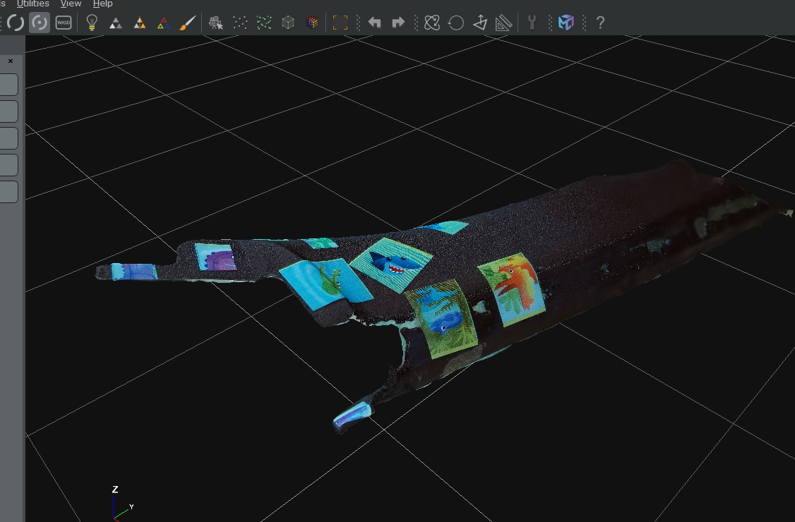
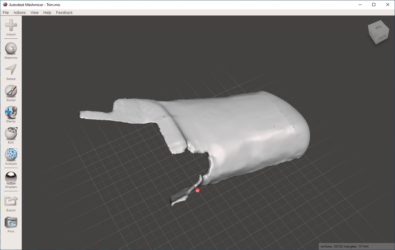
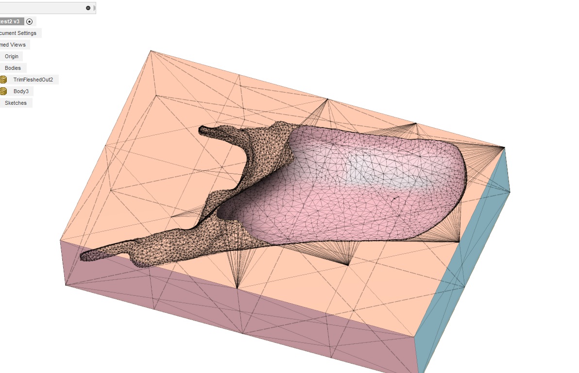
With the stickers and few spots (pennies) sprinkled around the background surface 3DF Zephyr was able to extract a usable point cloud and create a reasonable mesh for the part:
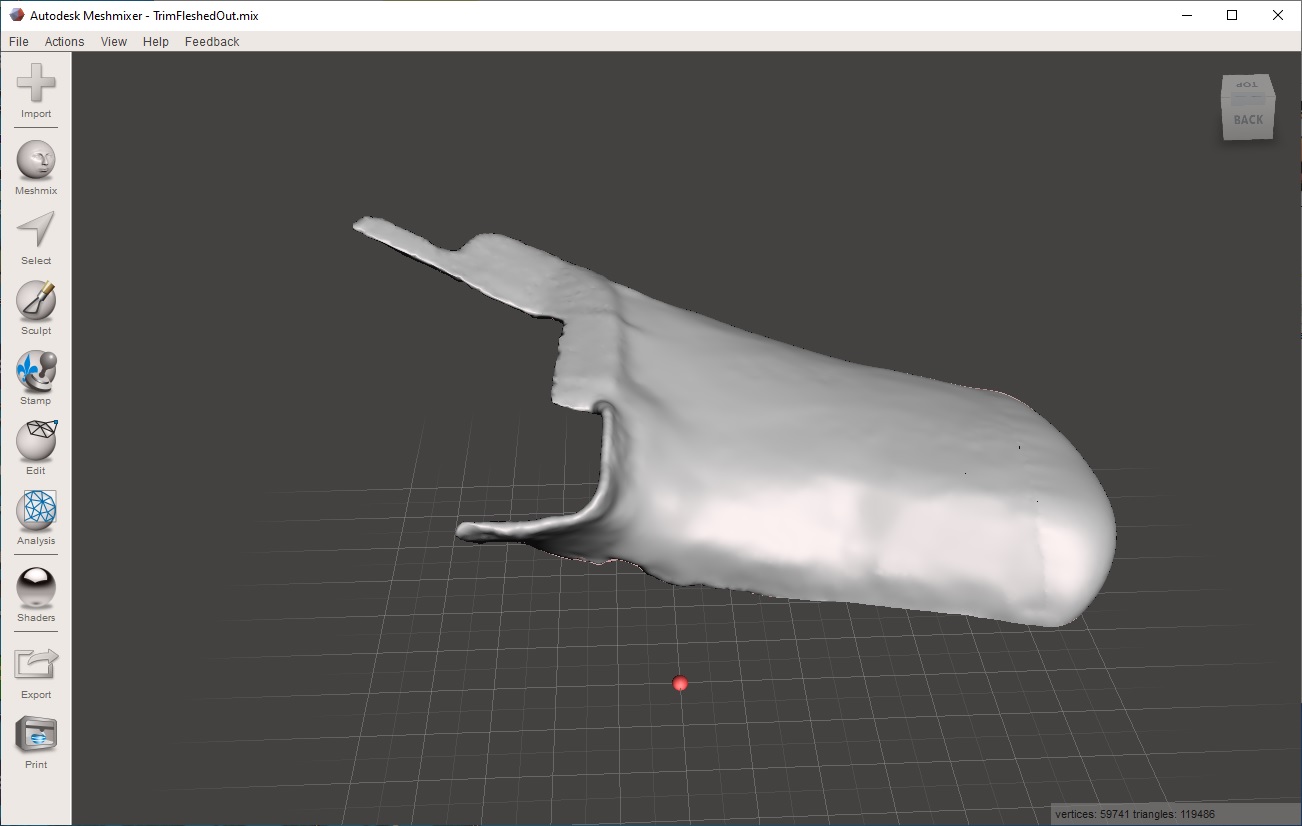
And after a lot of trial and error I was able to fill in the missing bits. At lease close enough that if I’m able to create the mold as I’m planning I should have some fiberglass that I can do the final shaping from:
But now my issue (well question) is how can I modify this so that I effectively pull the pattern straight “up” leaving a void in the mold that looks as if I pushed the pattern down into it?
Anyone have any suggestions? Or perhaps even some simple phrases for what I’m trying to accomplish that I can use to search for tutorials on youtube? I’m having little luck finding an example of what I’m trying to accomplish…
If it was a solid instead of a mesh/surface, you could do a boolean operation (a subtraction). I am far from a CAD expert, so I don’t know how to turn a mesh into a solid. I also wonder if there is a way to cut the block with the mesh, leaving two halves. But I haven’t seen that feature either.
I am a big fan of the shark, dinosaur, and alligator stickers.
Don’t change your camera settings between shots is what I wld add to Jeff’s answer. Lock the zoom if you can (rather at fully zoomed out) and disable the flash and autofocus (stay far enough from the object so it stays in focus). Without going technical, these have to do with the distortion effect and focal length estimation for each image which are some main challenges for the technique if not enough/good feature points are available as was mentioned already (you can further help the software with setting the focal length if there is such an option).
Now for shadows and based on my experience (also a CV developer here!), I wouldn’t try hard to eliminate them if it turned out to be difficult and as long as they are static (so don’t walk in front of your light sources and avoid shadows cast by the sun! It is true though that, depending on the surface, shadows can create extra confusing/bad features (particularly on synthetic surfaces) but also can be rich in features! (especially on organic surfaces). Remember that the Photogrammetry does not work for non-static scenes (commercial packages are probably capable of discarding few moving features but I doubt the free ones do anything of that sort)
Anyway, photogrammetry is an interesting tool for the fine people of this community so I thought to drop my 2 pennies.
how can I modify this so that I effectively pull the pattern straight “up” leaving a void in the mold that looks as if I pushed the pattern down into it?
I don’t have an answer to this specific question, but I think you are going to have a lot more options if you convert it from a mesh to Fusion 360 solid (BRep). High-triangle meshes don’t work very well in Fusion 360, so consider doing some remeshing and/or reducing in the Mesh workspace before converting.
If you want to share your STL file, I’ll be glad to play with it for a bit to see if I can figure out a workflow for what you want. STL files must be put in a ZIP file before they can be uploaded to the forum.
Apparently sometime in the last year F360 added a boatload of capabilities in the “Mesh” toolspace. You used to have to convert meshes to bodies in order to do much manipulation to them, but as of recently that’s no longer the case. The last image above was after doing a boolean combine against the original mesh and a second “mold body” block that was converted to a mesh. That’s a pretty significant improvement over having to convert the meshes into solid bodies before they could be manipulated much. I’m surprised I hadn’t heard about that update, but I didn’t and apparently it’s been there for almost a year(?)…
Anyway - @robertbu I’ll take you up on the offer and attach the stl. Thanks.

 This will probably be what I attempt next…